Protech, Installation, Alignment – Protech Audio 590B User Manual
Page 2: Program switch drawing, model 590b
INSTALLATION
The 590B Programmable Switching Card is designed to be
mounted in the Model 857B Card Frame or the Model 858B
Card Frame.
The Model 857B Card Frame will accomodate up to 10 audio
cards, and requires an external power supply (Model 66708).
The Model 858B Card Frame will accomodate up to 9 audio
cards, and has a built-in unpluggable power supply card.
Both card frame assemblies bus the DC power to the individual
card slots, and provide screw-type barrier termination points for
audio and DC connections.
The determination as to which backplane assembly to use in
your project, was made prior to our factory receiving the order.
The backplane assembly you have received will accommo-
date the group of cards you or your designer have specified.
4- Unpack each individual card, inspect for shipping
damage, and assuming none is found, slide the card
half-way into the appropriate slot. After all cards have been
installed half-way into the card frame, plug in one card at a time
and turn on the power supply. Make sure no unusual loading is
noticed at the power supply. If loading is noticed, turn off the
power supply, unplug the card and recheck terminations. If no
loading is noticed, continue inserting each card in the card
frame, checking power supply loading as each card is plugged
in. When all the cards have been plugged in, the installation is
complete, and all that remains is the alignment.
The Model 590B does not require alignment. The only adjust-
ments to the card are the switch settings which determine
the logic program to be used (See facing page).
Operation of the unit may be checked in the following
manner.
1- Apply power to Model 590B.
2- Apply a signal representative of the actual signal level to
be used, to contacts 1A & 1B inputs.
3- While monitoring contacts 1A & 1B outputs, ground
switch #1 (Pin 10). Check for proper signal level at the
output pins.
4- Repeat steps 3 & 4 for each switch channel on the
Model 590B. If the card is to be used in any program other
than independent, make switch ground closures in
sequence to check that the logic program is operating as
desired. If it is not, recheck program switch settings.
This completes the installation and alignment of your Model
590 Programmable Sswitching Card. The card(s) may be ex-
pected to deliver years of uninterrupted service.
Page 2
ALIGNMENT
The actual steps necessary for installation of the 590B Program-
mable switching card, are comparable to those necessary for
any of the INTEGRA III SYSTEM cards. They are as follows:
1- Mount the card frame in an appropriate EIA 19" width rack,
using 4 screws of sufficient tensile strength to provide secure
mounting.
2- A determination has been made as to which type of power
supply will be used on your system. Follow the instructions for
the type of power supply you will be installing.
EXTERNAL POWER SUPPLY. If an external power supply
is to be used, terminate the proper supply connections
to pins 1, 2, & 3 of the DC connector, as shown in the card frame
layout drawing Turn on the power supply, and using a DC
voltmeter, check for correct voltage and polarity at pins 1, 2, &
3 of of the DC cpnnector.
INTERNAL POWER SUPPLY. If a plug-in power supply card
is to be used, plug in the supply card, and check for proper
illumination of both plus and minus DC green LED's.
3- Terminate all audio input and output connections, using the
card connection drawing on the facing page. Shielded cable is
recommended for all audio connections.
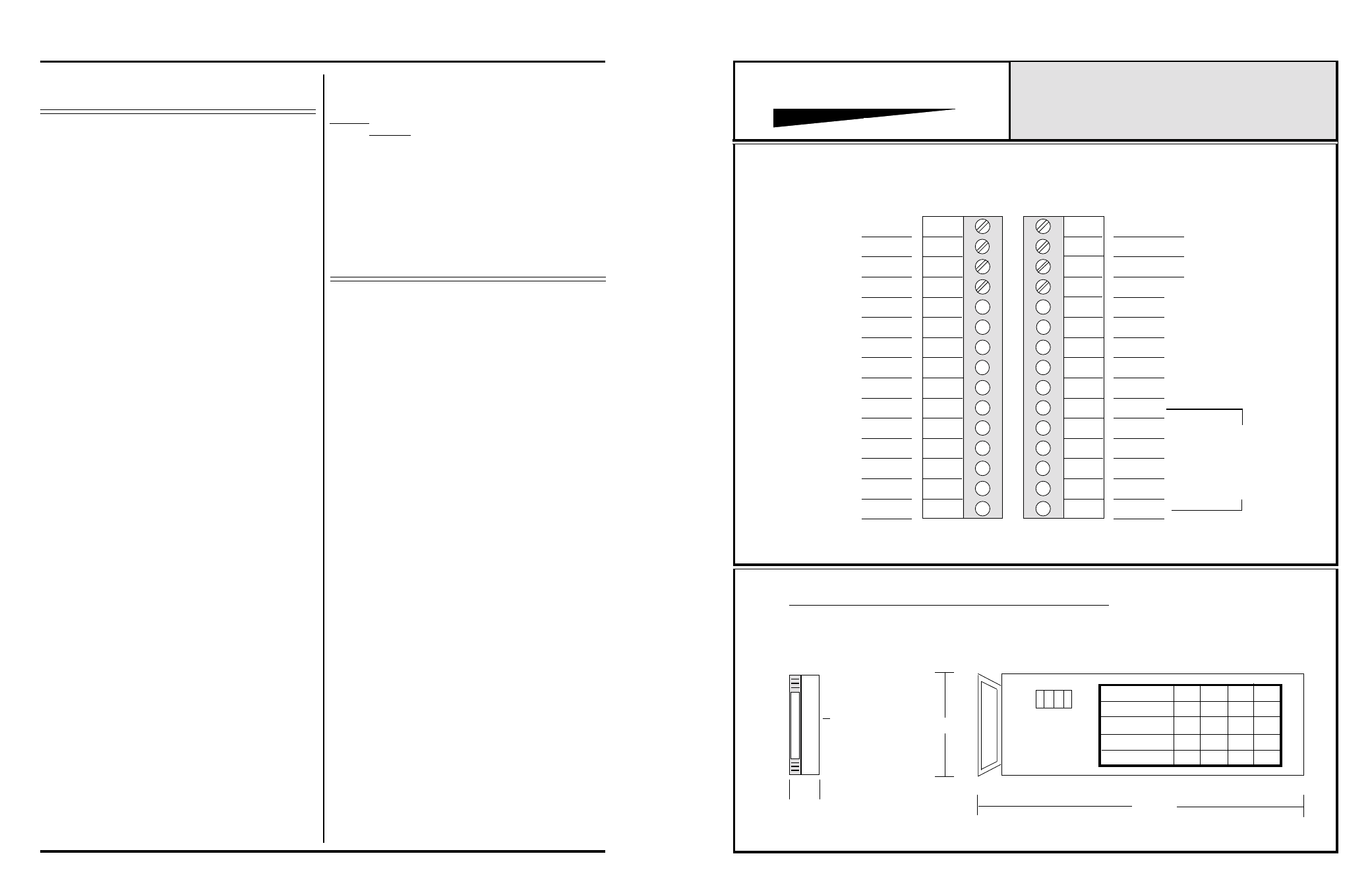
PROGRAM SWITCH DRAWING, MODEL 590B
SIDE VIEW
8.0"
2.5"
FRONT VIEW
0.75"
COMPONENT
SIDE
1
2
3
4
5
6
7
8
9
10
11
12
13
14
15
16
17
18
19
20
21
22
23
24
25
26
27
28
29
30
INTEGRA III SYSTEM
CONNECTOR & PROGRAM DRAWING
MODEL 590B
5A, IN
5A, OUT
GROUND
4B, IN
5B, OUT
5B, IN
LINK-1
GROUND
LINK-2
SWITCH 1
SWITCH 2
SWITCH 3
GROUND
4B, OUT
4A, IN
4A, OUT
3B, IN
3B, OUT
3A, IN
3A, OUT
2B, IN
2B, OUT
2A, IN
2A, OUT
1B, IN
1B, OUT
1A, IN
1A, OUT
4 3 2 1
FUNCTION
SW4
SW1
SW2
SW3
OFF
INDEPENDENT
OFF
ON
ON
LOCKOUT
OFF
OFF
ON
ALL ON
ON
ON
ON
ON
LAST ON
OFF
ON
ON
ON
SWITCH
OFF
SWITCH 5
SWITCH 4
857B & 858B Backplane Connections.
APPLY POWER TO
MODEL 590B
BEFORE MAKING
SWITCH CLOSURES
Note 1-
The alignment procedures for INTEGRA III SYSTEM cards,
differ from card type to card type. Therefore it is necessary
to consult the alignment procedure for each type of card being
installed, to properly align a card frame using different card
types.
PROTECH
®