Protech audio, Installation, Alignment installation – Protech Audio 588C User Manual
Page 2
INSTALLATION
Page 2
4- Unpack each individual card, inspect for shipping
damage, and assuming none is found, slide the card
half-way into the appropriate slot. After all cards have
been installed half-way into the card frame, plug in one
card at a time and turn on the power supply, unplug the
card and recheck terminations. If no loading is noticed,
continue inserting each card in the card frame, checking
power supply loading as each card is plugged in. When all
the cards have been plugged in, the installation is
complete, and all the remains is the alignment.
ALIGNMENT
INSTALLATION
The 588C Line Amplifier/Tone Control Card is
designed to be mounted in the Model 857/857B
Card Frame Package, or the Model 858/858B Card
Frame Package. The Model 857/857B Card Frame Pack-
age will accomodate up to 10 audio cards, and requires an
external power supply. The Model 858/858B Card Frame
Package will accomodate up to 9 audio cards, and has a
built-in, unpluggable power supply card.
Both card frame assemblies buss the DC power to the
individual card slots, and provide screw-type barrier termi-
nation points for audio and DC connections.
The determination as to which card frame assembly
to use in your project, was made prior to our factory
receiving the order. The card frame assembly you have
received will accommodate the group of cards you or
your designer have specified.
The actual steps necessary for installation of the Model
588C Noise Gate/Ducker, are comparable to those nec-
essary for any of the INTEGRA III SYSTEM cards. They
are as follows:
1- Mount the card frame in an appropriate EIA 19" width
rack, using 4 screws of sufficient tensile strength to
provide secure mounting.
2- A determination has been made as to which type of
power supply will be used on your system. Follow the
instructions for the type of power supply you will be
installing.
EXTERNAL POWER SUPPLY.
If an external power supply is to be used, terminate
the proper supply connections to pins 1, 2, & 3 of the
DC barrier connector , as shown in the card frame layout
drawing. Turn on the power supply, and using a DC
voltmeter, check for correct voltage and polarity at pins
1, 2, & 3 of the barrier connector.
INTERNAL POWER SUPPLY.
If a plug-in power supply card is to be used, plug in
the supply card, turn it on, and check for proper
illumination of both the positive and negative voltage
LED's, on the power supply card front panel.
3- Terminate all audio input and output connections,
using the card connection drawing on the facing page.
Double conductor shielded cable is recommended for
all audio connections. Terminate each unused input with
a 1K ohm resistor.
Each 588C has been shipped from the factory with the input
selector switch in the line input position, and the gain
aligned for unity gain (level in = level out with 600 ohm
load). The gate adjustments, and the ducking adjustment
have been set at the factory to the most used settings,
and should not require adjustment If other than unity
gain is required, the following alignment is recommended.
1- Select Mic or Line inputs, via slide switches mounted
onback end of PC Assembly.
2- Apply a signal representative of the actual signal to
be used to input #2 (ducked channel) and adjust gain
trimpot marked Duck on facing page, until the output
reaches the desired level. (Recommended output level is
-10 to 0dB).
3- Apply a signal representative of the actual signal
to be used to input #1 (gate channel) and adjust gain
at trimpot marked Gate on facing page, until the output
reaches the desired level (Recommended output level is -
10 to 0dB).
4-Adjust Attenuation trimpot, Attack and Release trimpots,
and Threshold trimpot, as necessary.
This completes the alignment procedure for the Model
588C Noise Gate/Ducker card. The card may be expected
to provide years of quality audio service.
INTEGRA III SYSTEM
PROTECH AUDIO
®
Page 3
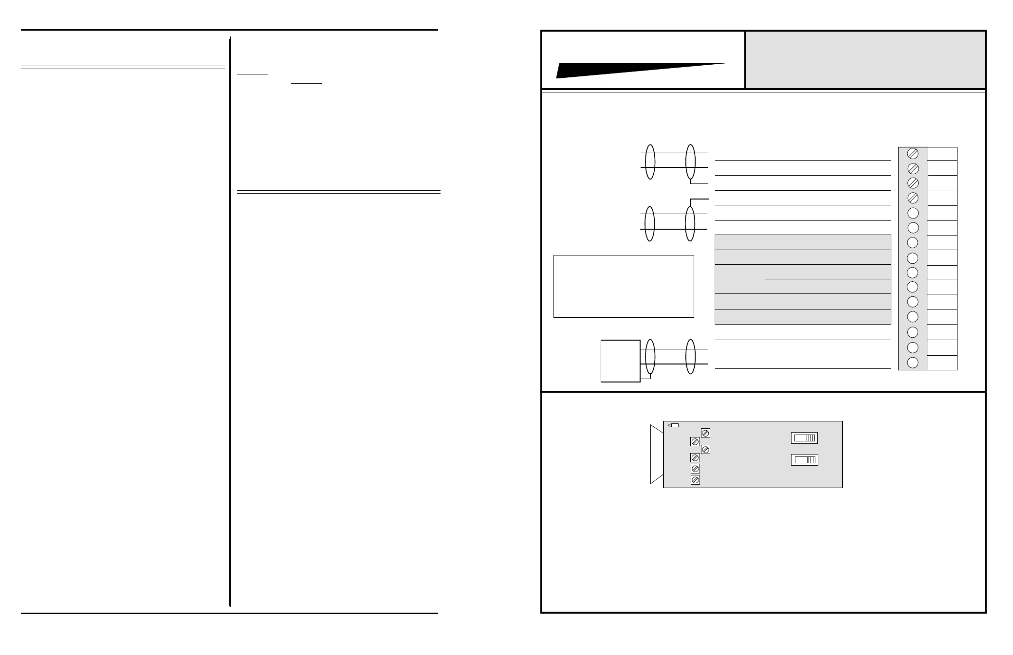
CONNECTOR & TRIMPOT DRAWING
MODEL 588C NOISE GATE/DUCKER CARD
Line
Mic
GATE CH.
Line
Mic
DUCK CH.
THRES
ATTN
LED
ATT
REL
GAIN-Duck
REL =
ATT =
ATTN =
THRES =
GAIN, Gate =
GAIN, Duck =
Release Trimpot, CounterClockwise = Slower Release
Attack Trimpot, Clockwise = Faster Attack
Attenuation (Duck) Trimpot, Clockwise = More Attenuation (Ducking)
Threshold Trimpot, Counterclockwise = Lower Threshold
Gate Channel Gain, Clockwise = More Gain
Duck Channel Gain, Clockwise = More Gain
800 SERIES BACKPLANE CONNECTIONS
1
2
3
4
5
6
7
8
9
10
11
12
13
14
15
Summing Junction Resistor Isolated Input
Summing Junction Resistor Isolated Input
Discrete Output, Duck Channel
Direct Summing Junction Input
Audio Output LO, Summed Output
Audio Output HI, Summed Output
Discrete Output, Gate Channel
Audio In LO, Duck Channel
Audio In HI, Duck Channel
Audio In LO, Gate Channel
Audio In HI, Gate Channel
GROUND
GROUND
GROUND
GROUND
Shaded Area Connections Are
Special Features,
Not Used in Normal
Noise Gate/Ducker Operation.
600-10K
Load
GAIN-Gate
Caution!
Mic Input has
Phantom Power