Proel PC260 User Manual
Page 12
12
14. RTA MIC input
This balanced XLR input is fitted a phantom power to supply and it can be used for connecting a condenser microphone for acoustic
measurements . This allows the PC260 to measure and display in real time the signal reproduced through the speakers system in the
acoustic environment .
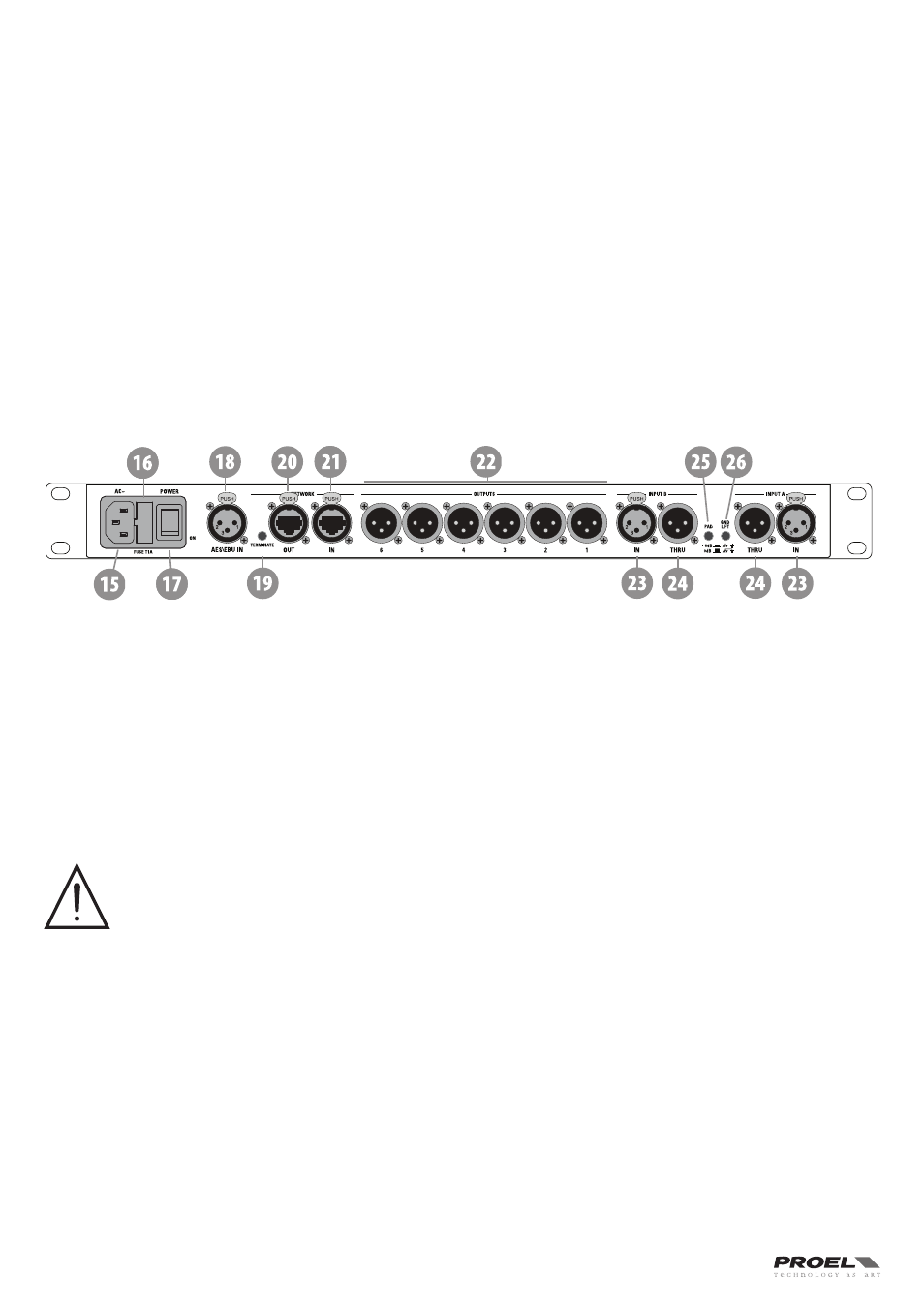
REAR PANEL
15. AC ~
The PC260 features a standard IEC A .C . inlet that will accept universal power cords . The PC260 power supply is auto-ranging and can
accept voltages from 100 - 240 V AC, 50 – 60 Hz . Only A .C . cords approved for use in your country should be connected to the PC260 .
16. FUSE holder
The A .C . inlet includes a fuse holder that contains the mains fuse as well as a spare fuse . If necessary, replace the fuse only with a
specified 5x20mm, T 1 A 250 V replacement . Disconnect A .C . power before replacing a fuse . Before turning the unit back on, assess
the condition of the A .C . receptacle powering the unit . If the fuse continues to blow, refer to PROEL qualified service personnel .
17. POWER switch
The A .C . power switch turns power to the PC260 On and Off .
18. AES/EBU Digital Input
In addition to the analog audio inputs, an AES/EBU digital stereo input is provided and selectable in the SETUP menu . The input
conforms to IEC standard 60958 Type I . Connections must be made with three-conductor, 110-Ohm, twisted pair cabling and an XLR
connector . It allows to use all sampling frequencies in the range of 32-96 kHz .
19. TERMINATE switch
In a PRONET network the last connected device must be terminated (with an inner load resistance) especially in a long run cabling:
press this switch if you want to terminate the unit .
20. PRONET Network OUT connector
This is a standard RJ45 CAT5 connector (with optional NEUTRIK NE8MC RJ45 cable connector carrier), used for transmission of remote
control data over long distance or multiple unit applications . See PRONET section further in this manual .
21. PRONET Network IN connector
This is a standard RJ45 CAT5 connector (with optional NEUTRIK NE8MC RJ45 cable connector carrier), used for transmission of remote
control data over long distance or multiple unit applications . See PRONET section further in this manual .
22. Balanced XLR Output connectors
Each output channel has an electronically balanced XLR connector for the connection to the system's amplifiers .
IMPORTANT: Care must be taken to assure that each output is connected to an appropriate amplifier and loudspeaker to
avoid damage or unexpected results . Note that a new preset may change the assignment of channel and its frequency
range . For instance an output assigned to Hi frequency speakers in one preset, may be assigned as a sub output in another .
See Configurations section further on this manual .
23. Balanced XLR Input connectors
Each input has an electronically balanced, locking XLR connector . In stereo or dual modes, connections to both inputs must be made .
In mono modes, only one connection is needed, typically to Input A .
24. Balanced XLR Thru connectors
Each analog audio input is linked directly to an XLR male connector . The signal does not undergo any digital conversion or processing .
These connectors are used to pass input audio to a second PC260 used as a slave or to other audio inputs in the system .
25. – 6dB PAD switch
Input levels to the PC260 can be reduced by 6dB prior to the A/D converter to compensate for higher-level output from mixers and
other audio devices . The PC260‘s Input level Meters (8) will indicate incoming signal level and whether attenuation is required .
26. GND LIFT switch
This switch lift the ground of the balanced audio inputs from the earth-ground of the PC260 . If you have HUM noise problem on the
whole loudspeaker system attached to your PC260 try to change the position of this switch . Please note that to have an effect all
cables must be balanced .