Parts identification, I/o panel – Posiflex JIVA KS-7212X User Manual
Page 4
Part 4
PARTS IDENTIFICATION
1. Main unit
2. Touch panel / LCD panel
3. Power indicator
4. Base stand
5. Optional side mount kit
6. HDD cover
CF memory card reader
7. Hinge cover
8. Base back cover
9. Cable exit
10. Power switch
11. LCD brightness up button
12. LCD brightness down button
13. Base back cover hook
14. USB ports on left side
15. Sundries trough for pencils, paper clips etc.
16. Rubber feet with fixing screws
17. Screw holes for base mount pole display kit
18. Cable tie (in the terminal’s back cover for desktop use only)
19. Cable tie (in the I/O plate for wall mount use only)
20. Oval cable passage on cast base trunk
21. Cable tie for all cables
22. Screw posts for optional HDD in base
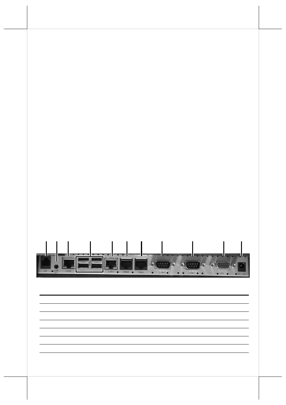
I/O Panel
Call out
Label
Description
A
CR
Controlling up to 2 cash drawers
B
LINE OUT
Audio Output
C
LAN2
LAN port, connecting to Ethernet
D
USB0-3
4 USB ports, connecting to USB devices
E
LAN1
LAN port, connecting to Ethernet
F
COM4
RJ45 Com port, connecting to peripherals
G
COM3
RJ45 Com port, connecting to peripherals
H
COM2
DB9 Com port, connecting to peripherals
A
C
E
F
H
J
D
G
I
K
B