Paloma MIC-180 User Manual
Page 9
5. Setting Hot Water Temperature
WARNING: Refer to the safety warnings in this instruction sheet and the water heater
instruction manual before setting the hot water temperature. Temperature can only be set or
changed with the main remote control (UMC-117) wired to the manifold controller.
NOTICE: DIP switch changes to adjust temperature are made on the manifold controller only.
Refer to the water heater instruction manual for setting hot water temperature. The default temperature
range of the main remote control is 100ºF to 120ºF (38ºC to 49ºC). It is possible to change the range
up to 180ºF (82ºC) by making the following adjustments.
Required adjustment for achieving 180ºF (82ºC) maximum water temperature setting (See figure
11 for DIP switch and button locations)
1. Turn off the remote controls. Turn off gas and water
supply to all water heaters in the manifold system.
2. Remove the front cover of the manifold controller
(MIC-180).
3. Find the DIP switch located below the LED display.
4. Change the DIP switch #4 setting on the main
communication PCB to the “ON” position (UP). DO
NOT alter any other DIP switch.
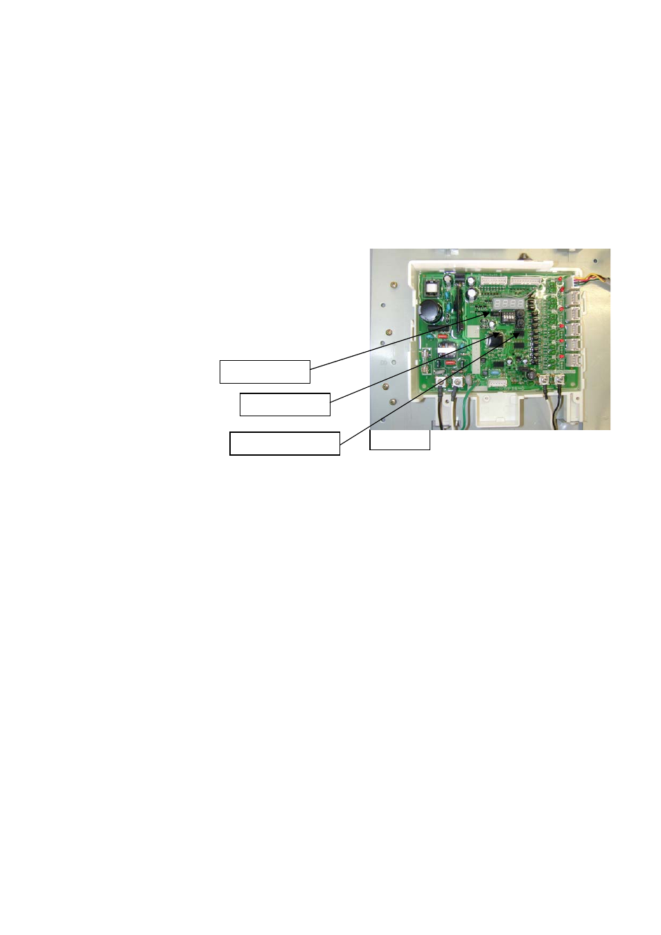
LED display
DIP switch
SW2/SW3 buttons
Figure 11
5. Press the SW2 button located below the LED display (See figure 11 for location of the button).
The LED display on the PCB displays “ON”.
6. When the LED displays “ON”, release the SW2 button.
7. Change the DIP switch #4 setting back to the “OFF” position (DOWN). DO NOT alter any other
DIP switch.
8. Attach the front cover of the manifold controller.
9. Turn on the remote control.
10. Restore gas and water supply for all water heaters in the manifold system.
11. Check and ensure safe operation and performance of water heaters.
12. See steps below to change the maximum temperature setting back to 120ºF (49ºC).
Required adjustment for changing setting back to 120ºF (49ºC) maximum water temperature
setting (See figure 11 for DIP switch and button locations)
1. Turn off the remote controls. Turn off gas and water supply to all water heaters in the manifold
system.
2. Remove the front cover of the manifold controller (MIC-180).
3. Find the DIP switch located below the LED display.
4. Change the DIP switch #4 setting on the main communication PCB to the “ON” position (UP) (See
figure 11 for location of DIP switch). DO NOT alter any other DIP switch.
5. Press the SW3 button. The LED display on the PCB displays “OFF”.
6. When the LED displays “OFF”, release the SW3 button.
7. Change the DIP switch #4 setting back to the “OFF” position (DOWN). DO NOT alter any other
DIP switch.
8. Attach the front cover of the manifold controller.
9. Turn on the remote control.
10. Restore gas and water supply for all water heaters in the manifold system.
11. Check and ensure safe operation and performance of water heaters.
-
9
-