Paloma MIC-180 User Manual
Page 7
NOTICE: The DIP switch settings on the water heaters must be changed for the water heaters to
be controlled by the manifold controller.
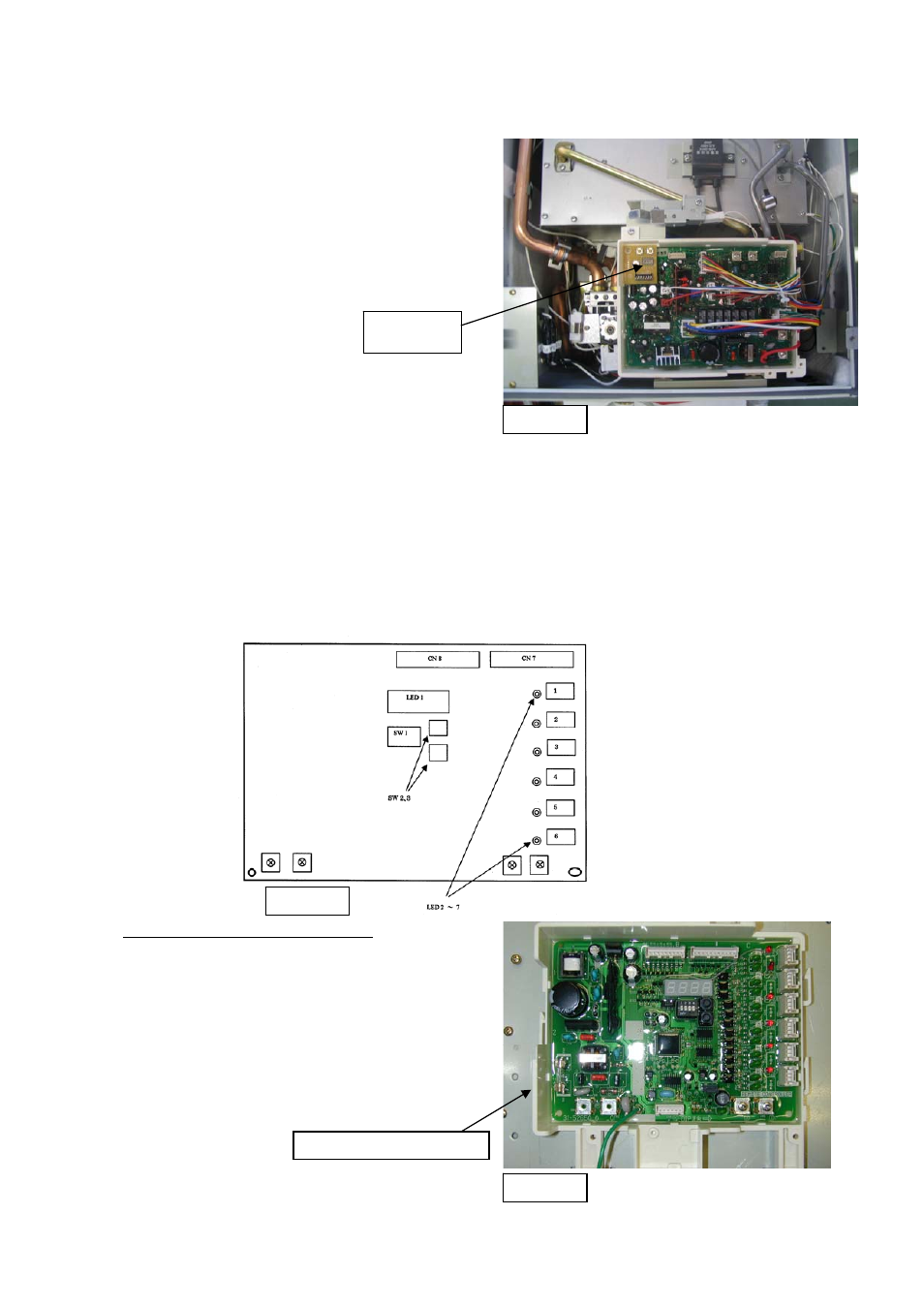
6. Change the DIP switch #4 setting on the PCB
of the water heater to “ON” position (UP) in
order to change the water heater to the
manifold installation mode. DO NOT alter
any other DIP switch. See figure 6 for DIP
switch location on water heater PCB.
Figure 6
DIP switch
7. Attach front cover of water heater.
8. If required, repeat steps 1 thru 7 to connect the communication cable to each of the water
heaters in the manifold system.
9. DO NOT turn on the power to the water heaters until all communication cables are connected
to the water heaters and the manifold controller.
4. Connecting and Wiring the Manifold Controller
4-1. Connecting and Wiring Main Communication PCB for Controlling Two (2)
to Six (6) Water Heaters
Figure 7
Schematic of main communication PCB
1. Disconnect power to manifold controller.
2. Remove the front cover of manifold controller.
3. Figure 7 shows the schematic drawing of main
communication PCB.
4. Figure 8 shows the main communication PCB.
5. Starting with the water heater No. 1 route the
communication cable through the opening at the
bottom of the manifold controller box as shown in
figure 9.
Main communication PCB
Figure 8
-
7
-