Paloma MIC-180 User Manual
Page 8
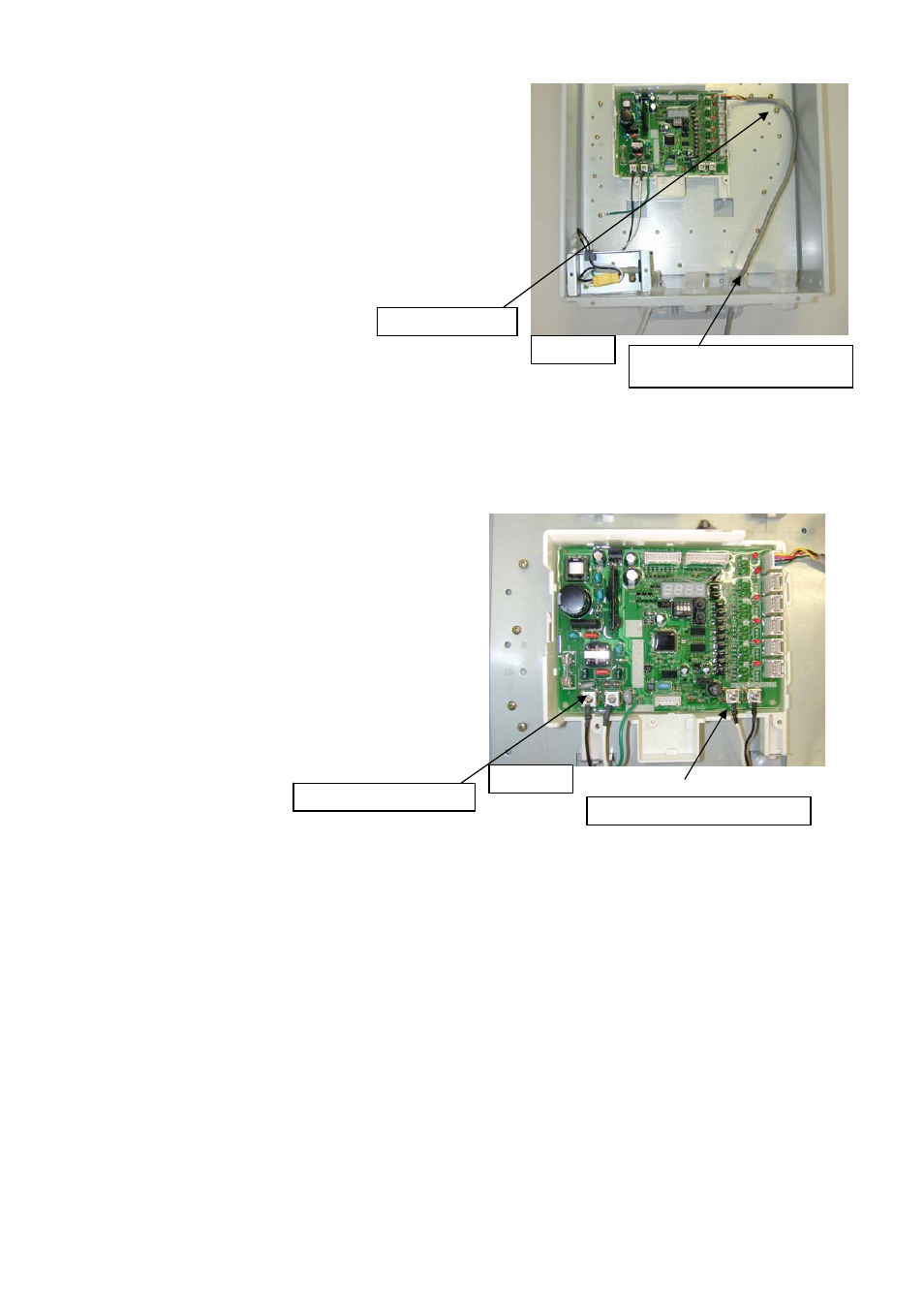
6. Connect the communication cable (MIC-K) from the
water heater to the connector socket on the right side of
the main communication PCB as shown in figure 9.
7. Fix communication cable with a clamp and one screw
as shown in figure 9.
8. Pull excess length of the communication cable into the
manifold box.
9. If required, repeat steps 1 through 8 to connect the
communication cable from each water heater in the
manifold system to manifold controller.
Clamp and screw
Communication cable from water
heater No.1
Figure 9
4-2. Connecting Main Remote Control to Manifold Controller
A main remote control (UMC-117) is provided with the water heaters. Install ONLY ONE (1) of these
main remote controls (UMC-117) to the manifold controller. This remote control will be used to
control the temperature of all water heaters in the manifold system.
NOTICE:
Temperature settings can ONLY be changed by
using the remote control connected to the
manifold controller.
The rest of the main remote controls can be used
to monitor the operations of each water heater if
installed per the water heater instruction manual.
Error codes, etc. will be displayed on the remote
control, but temperature settings cannot be
changed.
The connecting wires can be any Type-T 18 AWG
wire similar to a thermostat wire and is not
polarity sensitive.
Figure 10
120VAC power terminal
Main remote control terminals
1. Route the wires from the main remote control through the opening at the bottom of the manifold
controller box.
2. Connect the wires from the main remote control (UMC-117) to the terminals on the bottom right
corner of the main communication PCB as shown in figure 10.
NOTICE:
If water temperatures above 120
°F (49°C) are required the DIP switch on main communication
PCB needs to be changed. See section 5, “Setting Hot Water Temperature” on page 9 for
instructions.
An extended communication PCB (sold separately) is required if more than six (6) water heaters
are installed in a manifold system. See section 6, “Typical Installation of Extended Manifold
Controller” on page 10 for installation instructions of the extended communication PCB.
3. Attach the front cover of manifold controller once all cables and wires are attached to the main
communication PCB.
4. Turn power on to the system after all cables and wires are attached, and adjustments are
completed.
-
8
-