Location – Paloma MIC-180 User Manual
Page 4
See figure 1 for typical installations of a manifold controller and extended communication PCB with
multiple water heaters. An extended communication PCB is required for installation of more than six
(6) water heaters. The extended communication PCB and the communication cables are sold
separately.
NOTICE:
Install the water heater, water piping, and gas piping per installation instructions provided with
the water heaters. A shutoff valve should be installed at the inlet water pipe, outlet water pipe
and gas inlet line of each water heater to facilitate easy service.
2.
Installing the Manifold Controller
NOTICE: Follow instructions provided with the water heater for installing the water heater and
main remote control. The main remote control is provided with the water heater.
Location
The manifold controller (MIC-180) can be installed indoors or outdoors. The main remote control
(UMC-117) must be installed indoors and per instructions provided with the water heater.
2-1.
Mounting the Manifold Controller
Make sure the location of the manifold controller allows easy access for service and operation.
Wall studs should be utilized when mounting the manifold controller to the wall. Alternately, a suitable
piece of wood may be placed inside or outside of the wall to span the distance between the wall studs.
Fasten the water heater mounting brackets to the wood. In case of dry wall or concrete wall use dry
wall anchors or lag bolts.
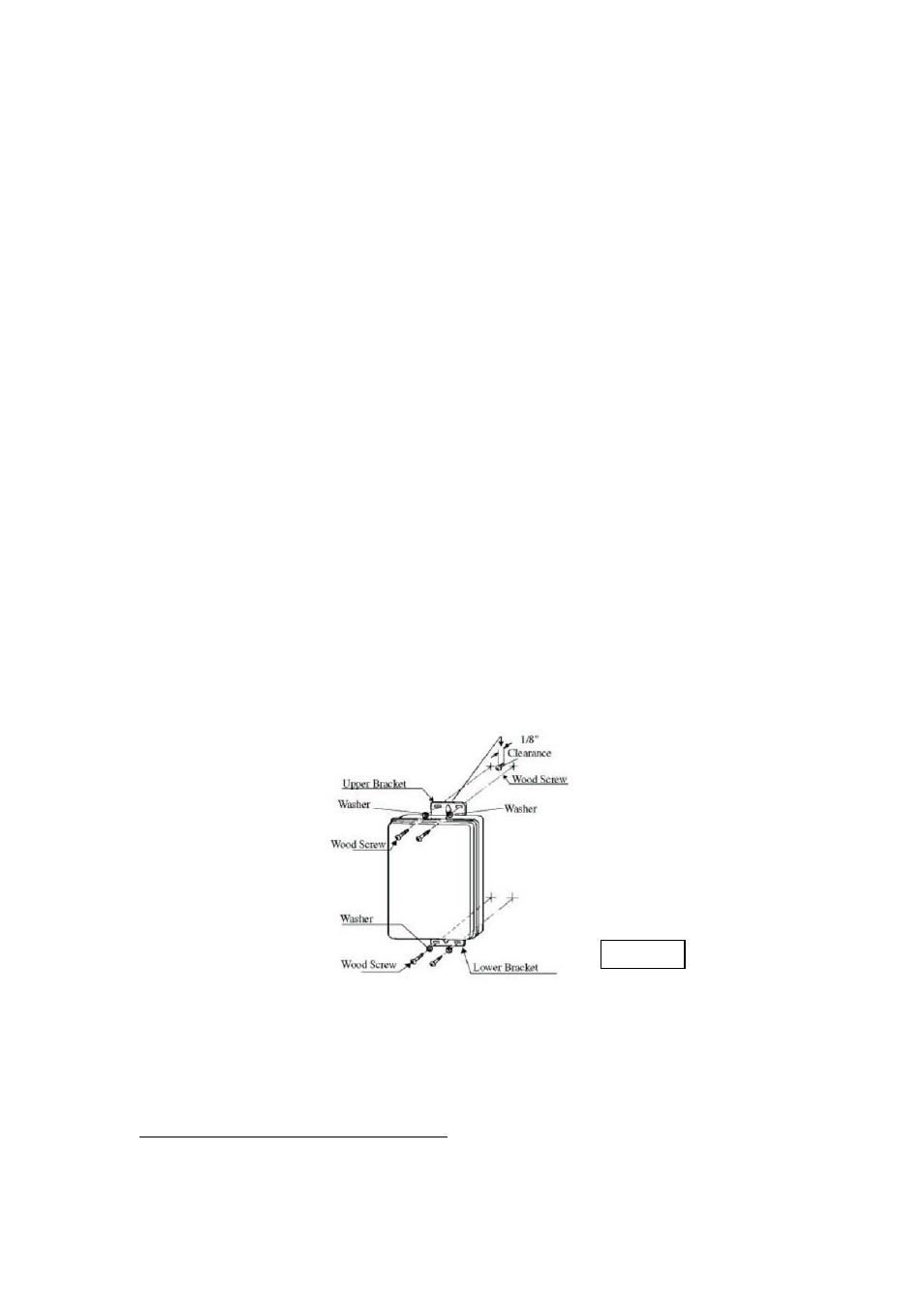
Install a wood screw for the upper bracket with a clearance of 1/8” (3 mm) between the wall and the
screw head. Hang the center of the upper bracket on the screw. Using a wood screw and washer, affix
the lower bracket to the wall (Left and right). Repeat to affix the top bracket. See figure 2 shown
below for typical mounting of the manifold controller.
The manifold controller requires 120VAC/60Hz. Have a receptacle with the ground terminal near the
manifold controller. The length of the power supply cord is 10 feet (3.05 m). If local codes require, or
if installed outdoors, the manifold controller should be hard wired.
Figure 2
2-2. Electrical Connections
WARNING: Field wiring connections and electrical grounding must comply with local codes, or
in the absence of local codes, with the latest edition of the National Electrical Code,
ANSI/NFPA 70, or in Canada, Canadian Electrical code, CSA C22.1 Part 1.
POWER CORD (INDOOR Installation Only):
• The electrical power supply requirement for this manifold controller is 120VAC/60Hz, 3
Amps.
• The manifold controller comes with a three (3) pin power supply cord.
-
4
-