Paloma MIC-180 User Manual
Page 11
6-1. Connecting and Wiring the Extended Manifold Controller
1. Follow the instructions in sections 1-4 for installing the water
heaters and main manifold controller.
2. Disconnect power to the manifold controller.
3. Remove the front cover of manifold controller.
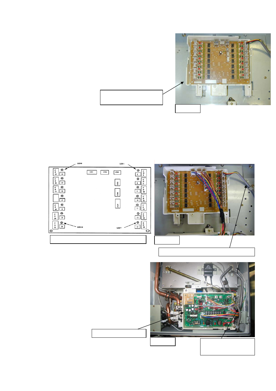
4. Install the extended communication PCB (MICS-180) with
one screw to the manifold box directly above the main
communication PCB as shown in figure 13.
Figure 13
Extended communication
PCB
5. Route the communications cable up through the opening at the bottom of the manifold
controller.
6. Connect the communication cable (MIC-K) from water heaters 7 through 20 to the connectors
on the right or left side of the extended communication PCB (MICS-180) as shown in Figure 14.
7. Fix each communication cable with a clamp and one screw as shown in figure 14.
8. Pull excess communication cable into the manifold box.
Schematic of extended communication PCB
Communication cable from water heater No. 7
Figure 14
9. Connect the relay cable between main
communication PCB and extended
communication PCB as shown in figure 14.
10. Figure 15 to the right shows the water heater
PCB with the communication cable connected.
11. Attach front cover of manifold controller.
12. Turn the power on to the manifold controller and
the water heaters, once all communication cables
from the water heaters are connected to the
extended communication PCB.
Communication cable
from manifold controller
Figure 15
Water heater PCB
-
11
-