Paloma MIC-180 User Manual
Page 3
1. Manifold Installation Control System (MIC-180)
The manifold installation control system (MIC-180)
consists of a main communication PCB for
manifolding two (2) to six (6) water heaters, mounting screws, manifold box, power supply cord, and
connector for optional hardwiring.
Manifold controller (MIC-180) provides control of two (2) to six (6) water heaters when properly
installed and connected with communication cables (sold separately) to any Rheem-Ruud or Paloma
commercial Tankless Water Heaters. To control additional water heaters (7 to 20 water heaters), it is
necessary to purchase an extended communication PCB (MICS-180) separately and install in the
control system. See section 6, “Typical Installation of Extended Manifold Controller” on page 10 for
instructions on installing extended communications PCB.
This instruction sheet outlines the configuration and installation for manifolding two (2) to twenty (20)
water heaters.
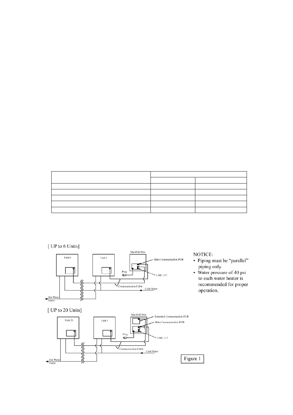
NOTICE:
No other manufacturer’s controls are suitable with Rheem-Ruud or Paloma Commercial
Tankless Water Heaters. Do not attempt to disassemble any of the controls or components.
1-1. Optional Parts
• Extended communication PCB (MICS-180) for manifold control of seven (7) to twenty (20)
water heaters
• Communication cable (available in 16 ft (4.87 m), 32 ft (9.75 m), and 65 ft (19.81 m) length)
Number of Water Heaters
Components
2 ~ 6 Units
7 ~ 20 Units
Manifold controller (Basic Unit) - MIC-180
1
1
Extended communication PCB - MICS-180
+
Not applicable
1
Communication cable (16 feet) - MIC-K-16*
2 ~ 6
7 ~ 20
Communication cable (32 feet) - MIC-K-32*
2 ~ 6
7 ~ 20
Communication cable (65 feet) - MIC-K-65*
2 ~ 6
7 ~ 20
+
Extended communication PCB (MICS-180) includes one relay cable and one screw.
* Communication cables include two clamps and two screws.
1-2. Typical Manifold Installation
-
3
-