Orion System Zoning User Manual
Page 25
Orion Systems
25
Zoning Design Guide
Modular Power/Communication Wiring
As previously described, VAV/Zone Controllers, the
Modular System Manager and the Modular Polling
Device, power and communications wiring is achieved
by using a Power/Comm distribution board and prefab-
ricated modular cables. The items below must be con-
sidered when sizing and wiring the modular devices:
•
Size the transformer for the correct VA load
based on the type and number of devices to
be connected to each Power/Comm Board.
The largest transformer that may be used to
power the Power/Comm Board is 100VA.
For transformer sizing of devices with
modular connectors, see Figure 1-17.
•
Do Not Ground The Power/Comm Board
Transformer!
If the Power/Comm Board transformer is
connected to earth or chassis
ground, the
Power/Comm Board and all devices
connected to it will be damaged.
•
Each Power/Comm Board has 4 individual
branch circuit connectors. No more than 6
devices may be connected to an individual
branch circuit. If more connections are
needed, add another Power/Comm Board.
•
The maximum total length of cables allowed
on a single branch circuit is 240 feet. If
distances to the devices would be greater than
this, add another Power/Comm Board at a
location that is closer to the farthest
controller(s).
The modular wiring and prefabricated cables virtually
eliminate power and communications wiring errors.
Simply plug in the cables between modular connectors.
Prefabricated Power/Comm Cables are available in 25,
40, 80 and 120 feet lengths. Power/Comm Extension
Cables are available in 10 and 20 feet lengths. With
these cable assemblies and extensions, almost any com-
munications cable length desired can be achieved with
the least number of connections. Always use the short-
est Power/Comm Cable Assembly between devices so
as not to exceed the maximum branch circuit cable
length requirement of 240 feet.
Communication Loops
The Orion system utilizes two different communica-
tions loops. These are the network loop and the local
loop. Communication between devices on each local
loop are via a 9600 Baud communication rate. Com-
munications between devices on the network loop uti-
lize a 19200 Baud communications rate. All modular
controllers (as previously discussed under the modular
power wiring) are connected by modular cable and will
not be discussed. All other controllers use terminal to
terminal wiring for communications. Please refer to the
following information for proper communications wir-
ing of the Orion system.
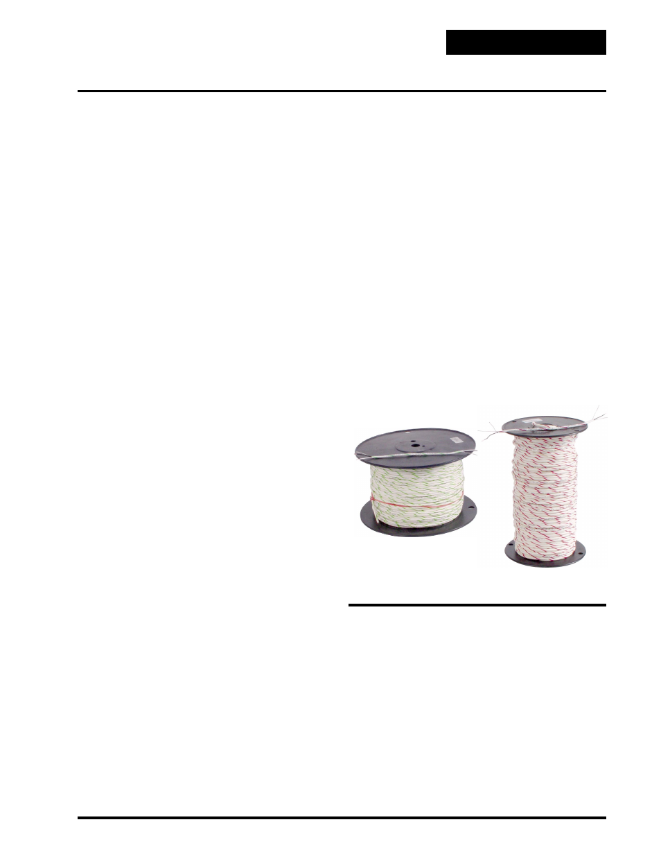
WattMaster requires that all communication wire be 18
gauge minimum, two wire shielded cable, Belden
#82760 or equivalent. WattMaster offers communica-
tions cable for this purpose. The 18 gauge color coded
and labeled wire is available for the local loop and the
network loop communications wiring. The local loop
wire is supplied in 1000 ft. spools and is labeled “Local
Loop” with a green candy stripe. The network loop
wire is supplied in 500 ft. spools and is labeled “Net-
work Loop” with a red candy stripe.
The loop is best connected in a daisy chain configura-
tion, meaning the loop is connected from one control-
ler to another. It is not necessary to sequentially ad-
dress the zone controllers in relation to their location
on the loop.
Figure 1-14: WattMaster Communications Wire
Local Loop Wire
Network Loop Wire