Zoning design procedures – Orion System Zoning User Manual
Page 14
14
Orion Systems
Zoning Design Guide
Zoning Design Procedures
General
There are six basic steps to designing an Orion Zoning
system:
1.) Determining the number and location of zones
2.) Sizing the central unit
3.) Duct Considerations
4.) Room air motion and diffuser selection
5.) Bypass damper sizing
6.) Sizing the zone dampers
Step #1 - Determining The Number And
Location Of Zones
A single HVAC unit should have no more than twenty
zones and no fewer than 3 zones. If the number of zones
exceeds twenty, then more than one HVAC unit may
be required to service the zones. Please consult the fac-
tory for situations that are borderline.
The primary precaution to be taken in applying the Orion
Zoning System is to select the zoning so that no zone
will be at maximum (design) heating (or cooling) load
when any other zone requires the opposite temperature
air to satisfy its load. For example, depending on the
wall, ceiling and floor material and location within the
building (e.g. top or middle floor), a typical floor of a
building usually has several distinct temperature or con-
trol zones that are affected uniquely by the outdoor load.
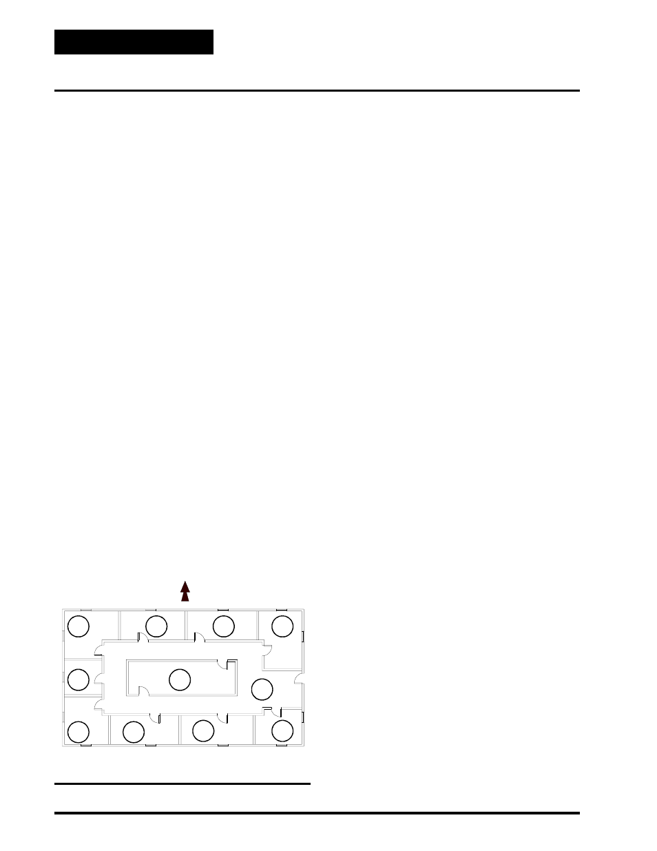
These zones are depicted in Figure 1-2.
Depending on the size of the building and partition lay-
out, some of these zones may overlap or be insignifi-
cant from a zoning standpoint. For example, Zone 11
could be multiple conference or computer rooms where
additional zoning would be required, or it could be as
small as a corridor where no zoning is required. Simi-
larly, zones 7 and 8 could have no external windows
and no partitions between them and could be consid-
ered a single zone. Some zones could be divided into
multiple offices with full partitions between them, thus
requiring separate Zone Controllers because of differ-
ent internal loads, but the same external load.
Generally, the greater the number of individual Zone
Controllers, the greater the comfort. The designer will
have to look at the specific building, balancing the costs
of multiple zones with the added comfort possible with
multiple zones, to match the owner’s requirements.
It is important to recognize that there are purely inter-
nal zones, such as Zone 11 in Figure 1-2, which may
contain separate offices/conference/computer rooms.
These internal zones could easily have high cooling re-
quirements while external zones (1,2,3, etc.) could be
at or near design heating load. This is a misapplication
of the Orion, zoning (or any heating/cooling change-
over) system. The interior zones with cooling only loads
should be served by a separate single zone rooftop
HVAC unit (that could be zoned between multiple rooms
with a similar load profile). Supplemental heat could
be added to the perimeter zones and controlled with the
auxiliary heat control board from the Zone Controller.
System performance will generally be compromised and
frequent change-over from the heating to the cooling
mode will occur during the heating season if purely in-
ternal zones are combined on the same air-condition-
ing unit serving perimeter zones. The exposure to the
sun has a large affect on the loading of the building.
With the building zoned as shown below, for the best
control, zones 6, 7, 8, 9 and 10 should be put on one
HVAC unit, and zones 1, 2, 3, 4 and 5 on another HVAC
unit. Zone 11 should be on a separate single zone con-
Figure 1-2: Zones Affected by the Outdoor Load