Troubleshooting, Led diagnostics & alarms, Preheat-x technical guide – Orion System PREHEAT-X User Manual
Page 21: Led diagnostics, Status leds, Diagnostic leds, Communication led, Relay leds, Binary input leds
PREHEAT-X Technical Guide
TROUBLESHOOTING
21
LED Diagnostics & Alarms
LED Diagnostics
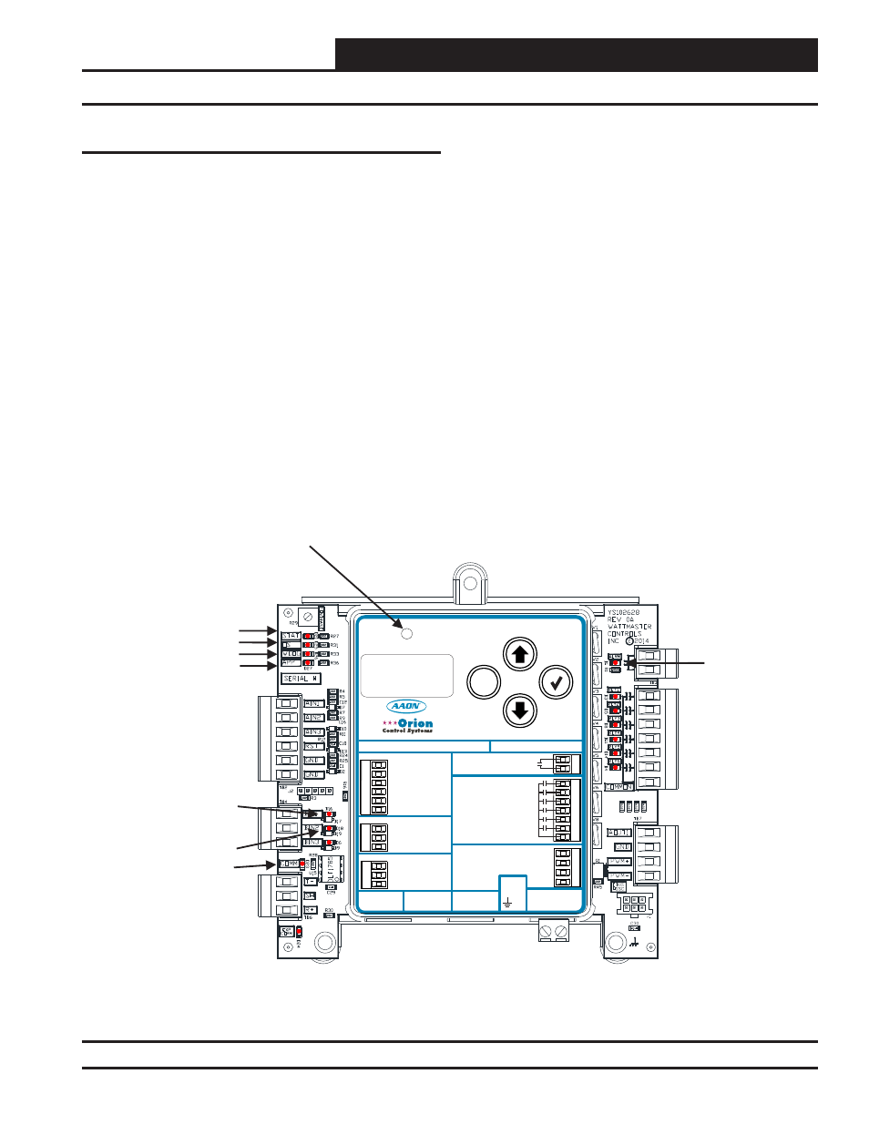
The PREHEAT-X Controller is equipped with LEDs that can be
used to verify operation and perform troubleshooting. See Figure
6, below for the LED locations. The LEDs associated with these
inputs and outputs allow you to see what is active without using a
voltmeter. The LEDs and their uses are as follows:
STATUS LEDs
POWER
- This green LED will light up to indicate that 24 VAC
power has been applied to the controller.
Diagnostic LEDs
ALARM
- This red LED located on the PREHEAT-X Controller’s
cover above the LCD display will light up to indicate an alarm. The
type of alarm(s) will be shown on the LCD display.
Communication LED
COMM
- This yellow LED will light up and blink when communica-
tions are detected.
Relay LEDs
RLY 1-6
- These green LEDs will light up and stay lit as long as the
Heat Relay(s) is active.
Binary Input LEDs
HEAT EN
- This green LED will light up when Heat is enabled.
EMERGENCY SHUTDOWN
- This green LED will light up when
Emergency Shutdown is enabled.
Figure 6: PREHEAT-X Controller LED Locations and Descriptions
M
ENTER
UP
DOWN
ALARM
MENU
ALARM CONTACT
HEAT 1
HEAT 2
HEAT 3
HEAT 4
HEAT 5
HEAT 6
RLY COMM
HEAT
OUTPUTS
ANALOG
OUTPUTS
0-10V MOD. SCR
GND
PWM +
PWM -
OE377-26-00061 PREHEAT-X
AAON No.: V48510
WattMaster Label
Rev.: 1D
#S
000062
W
E-BUS
CONNECT
E-BUS
CONNECT
LAT1
0-10V RESET
LAT2
EAT
GND
GND
ANALOG INPUTS
BINARY INPUTS
RS-485 COMM
+24 V
A
C
GND
www.aaon.com
ENABLE
T(-)
EMERG. SHUTDOWN
SHLD
FUTURE USE
R(+)
CONTACT RATING IS
1 AMP MAX
@ 24 VAC
www.orioncontrols.com
MSTP
BACnet
OS LED
WDOG LED
APP LED
STAT LED
ALARM LED
HEAT ENABLE LED
COMM LED
EMERGENCY
SHUTDOWN LED
ALARM LED