OnLine Power Power Wave 4 User Manual
Page 99
6005-145 Rev. A
9-14
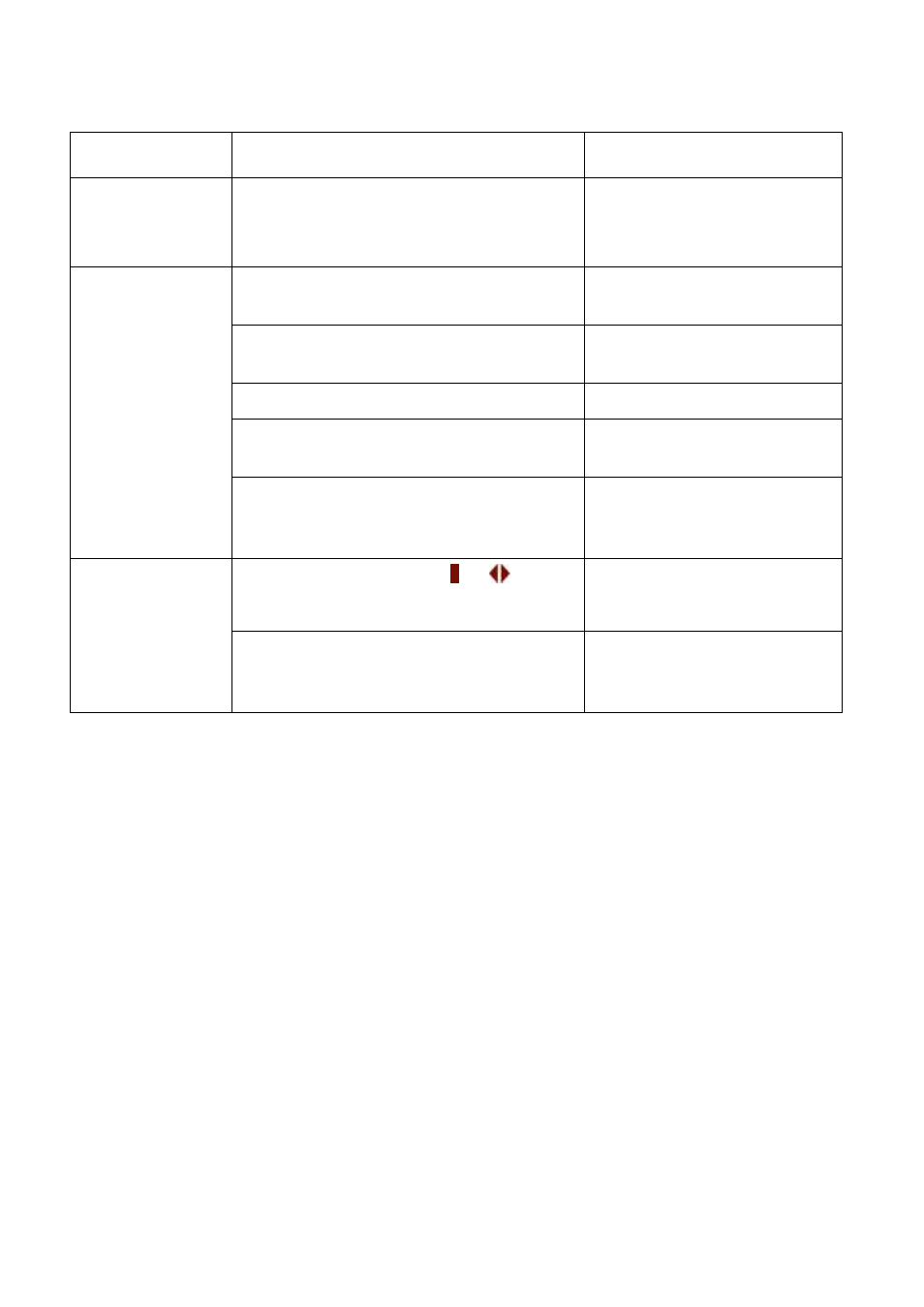
Abnormal
Description & Checkpoint
Solution
(14) All LED in
the front panel
light up.
CPU inserting error in 3A or 3R PCB
Insert the CPU into correct
socket.
(15)
Communication
interface is not
working
properly.
Communication cables are connected
improperly.
Correct the wiring.
Communication software is not
installed successfully.
Reinstall the software.
Communication port setup error.
Correct the setup.
CPU inserting error in 3R PCB.
Insert the CPU into right
socket.
If the abnormal cannot be corrected
after the solution actions have been
taken.
Refer to PCB LED
Detecting Guide and check
the 3R PCB.
(16) The
inverter has
been turned on
but no action of
inverter.
The inverter switches of &
are not
pressed simultaneously.
Try to press these two
buttons simultaneously
PCB Connection is not good.
Refer to PCB LED
Detecting Guide and check
the connection of 3W PCB.