Res erve mode inverter mode – OnLine Power Power Wave 4 User Manual
Page 22
6005-145 Rev. A
1-11
Usually, the most frequent failures of the ELI occur at the inverter. Therefore,
we have added redundant protection circuitry to protect the inverter. A strong
snubber is added to suppress the spikes and noise, oversized, high quality
components are used throughout, semi-conductor fuses are provided, and
ventilation is maximized. The result of this design is a more rugged, reliable and
high efficient inverter. At the same time, the inverter can sustain overload and
high peak current drawn by the load. Additionally, a longer MTBF is achieved.
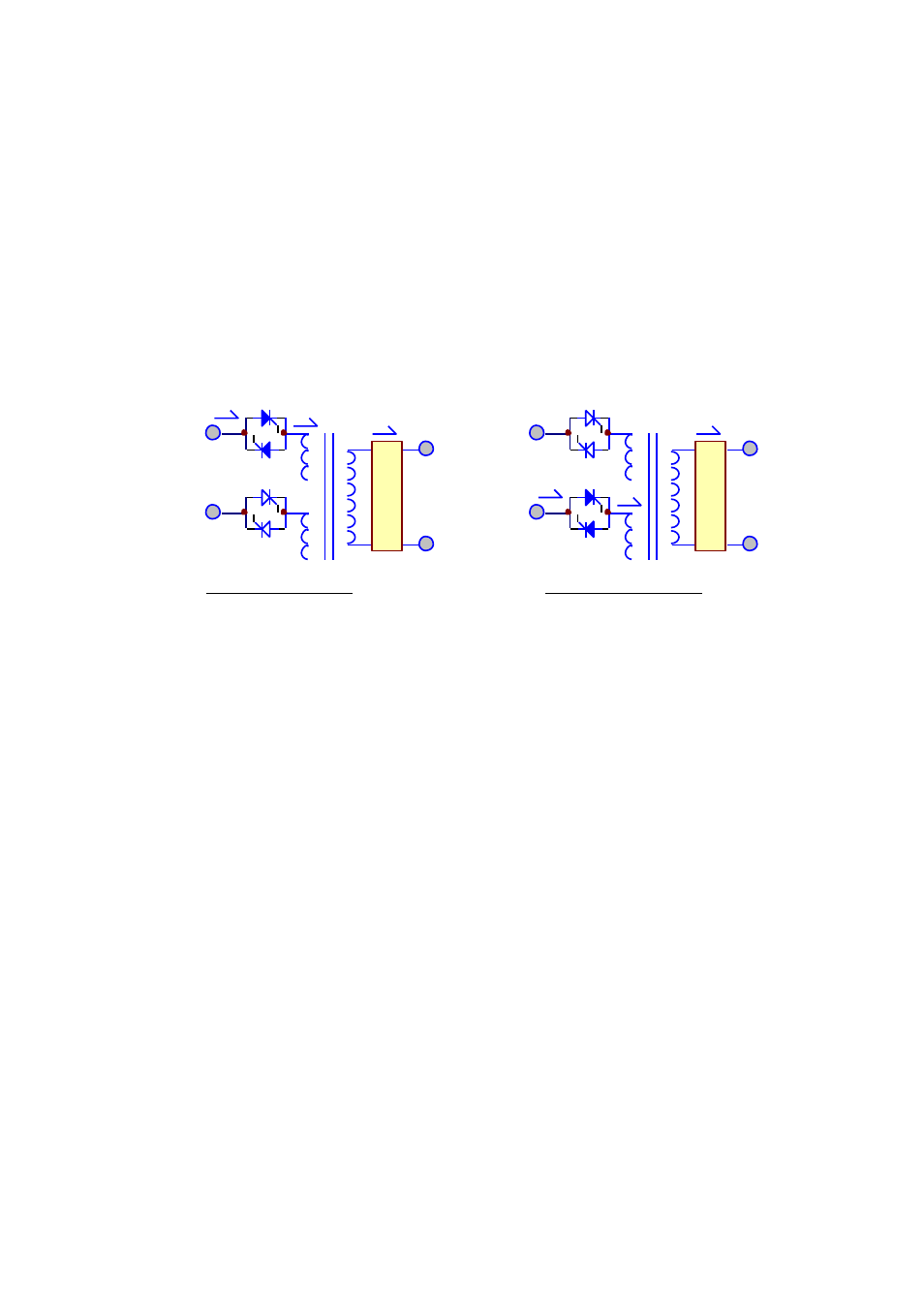
1.5. Static Switch
The static switch is composed of two pairs of SCRs, connected back-to-back.
The switch can transfer the load from reserve to inverter or from inverter to
reserve without losing power at the output. Therefore, it is a very important
portion of a ELI.
Detection circuitry is added to the control circuit to achieve zero dead time
transfer. Extra detection logic is employed to control when the static switch
should transfer. For example, when output is short circuited, under normal mode
operation, the ELI detects the short circuit and stops the inverter. The static
switch will not transfer power to the reserve circuit, which might damage the
reserve breaker. In case of an overload, the ELI will stop the inverter after a
period the inverter can endure, and then transfer the load to the reserve circuit,
since the overload capability of the static switch is higher than the inverter.
The transfer action is determined according to the reserve-input voltage and
frequency to protect supplying incorrect power to the load. Finally, there is a
double check by the CPU as to whether the transfer is successful or not.
F
I
L
T
E
R
T
O
L
O
A
D
RESERVE
F
I
L
T
E
R
T
O
L
O
A
D
INVERTER
RESERVE
INVERTER
RES ERVE MODE
INVERTER MODE