ONICON F-5200 Inline User Manual
Page 17
11451 Belcher Road South, Largo, FL 33773 • USA • Tel +1 (727) 447-6140 • Fax (727) 442-5699 • [email protected]
F-5200 Inline Thermal Mass Flow Meter Manual 05/14 - 0763-4 / 19476
Page
17
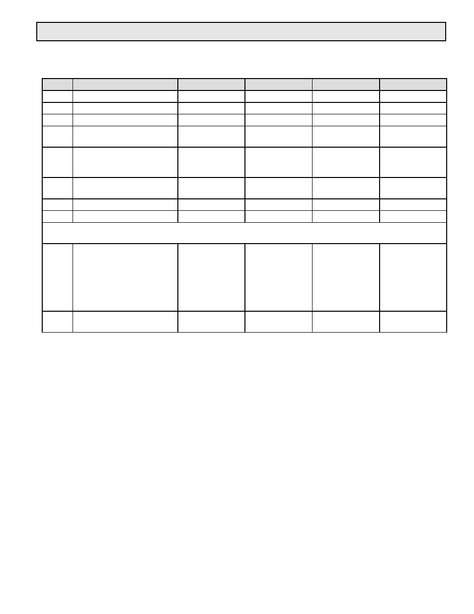
4.3 START-UP & COMMISSIONING WORKSHEET
Please read all installation instructions carefully prior to proceeding with these steps. Use the
following worksheet for checking off the commissioning steps and recording measured values.
STEP
TEST/MEASUREMENT
S/N:
S/N:
S/N:
S/N:
1.
Meter location:
2.
Confirm pipe size:
3.
Confirm orientation:
4.
Control system
programming:
5.
Match display
serial number
(S/N) if ordered:
6.
Signal connections
verified:
7.
Supply voltage verified:
8.
Connect power:
The following steps require flow in the pipe. Flow signal readings should be taken while holding the flow rate
constant, if possible. Otherwise, take the various output readings as quickly as possilbe.
9.
Analog or pulse output(s)
4 - 20 mA signal:
Scaled output interval:
Calculated flow rate:
__________mA
____________
_______SCFH
__________mA
____________
_______SCFH
__________mA
____________
_______SCFH
__________mA
____________
_______SCFH
10.
Flow rate displayed by con-
trol system:
_______SCFH
_______SCFH
_______SCFH
_______SCFH