ONICON F-5200 Inline User Manual
Page 12
11451 Belcher Road South, Largo, FL 33773 • USA • Tel +1 (727) 447-6140 • Fax (727) 442-5699 • [email protected]
F-5200 Inline Thermal Mass Flow Meter Manual 05/14 - 0763-4 / 19476
Page
12
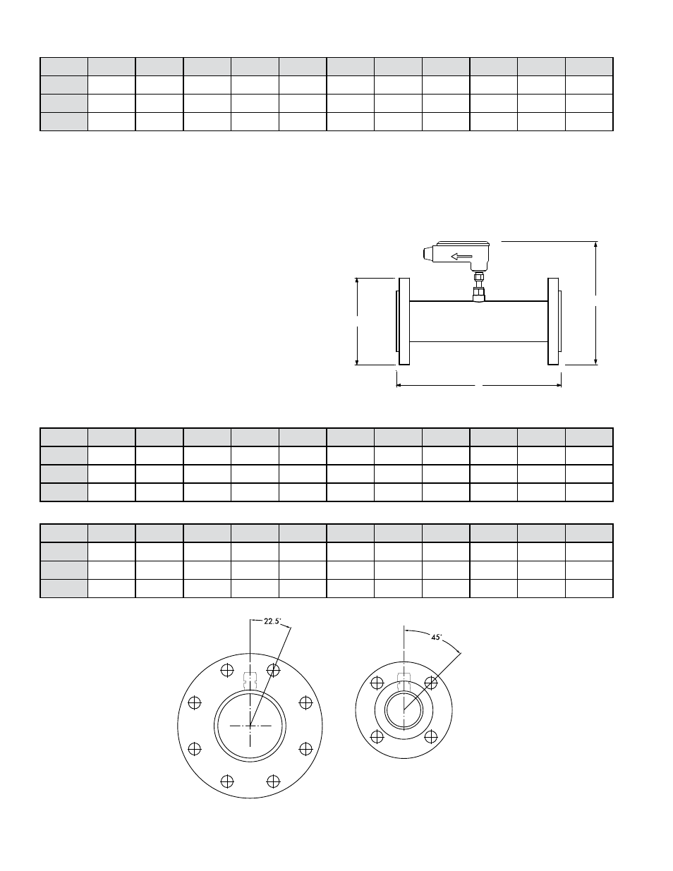
ANSI Class 150 Flanged inline sensor dimensions (inches)
ANSI Class 300 Flanged inline sensor dimensions (inches)
Bolt pattern for 4”
flanged meter
Bolt pattern for
½” - 3” flanged meter
¼
⅜
½
¾
1
1¼
1½
2
2½
3
4
L
n/a
n/a
7
8
10
12
12
12
12
12
12
D
n/a
n/a
3.5
2.88
4.25
4.62
5
6
7
7.5
9
H
n/a
n/a
12.38
12.76
13.13
13.5
13.88
14.88
15.88
16.38
17.88
¼
⅜
½
¾
1
1¼
1½
2
2½
3
4
L
n/a
n/a
7
7
8
10
12
12
12
12
12
D
n/a
n/a
3.75
4.62
4.88
5.25
6.12
6.5
7.5
8.25
10
H
n/a
n/a
12.63
13.5
13.76
14.13
15
15.38
16.38
17.13
18.88
3.2.2 Flanged Meter
FLOW DIRECTION
D
L
H
D
L
H
FLOW DIRECTION
Installation Instructions
1.
Apply AGA approved paste sealant or tape sealant to the male NPT threads.
2.
Tighten fittings as per ANSI standards for NPT pipe fittings.
3.
Leak test all connections.
¼
⅜
½
¾
1
1¼
1½
2
2½
3
4
L
6
6
7
8
10
12
12
12
12
12
12
D
0.54
0.68
0.84
1.05
1.315
1.66
1.9
2.375
2.875
3.5
4.5
H
9.42
9.56
9.72
9.93
10.195
10.54
10.78
11.255
11.755
12.38
13.38
Threaded inline sensor dimensions (inches)