ONICON F-5200 Inline User Manual
Page 14
11451 Belcher Road South, Largo, FL 33773 • USA • Tel +1 (727) 447-6140 • Fax (727) 442-5699 • [email protected]
F-5200 Inline Thermal Mass Flow Meter Manual 05/14 - 0763-4 / 19476
Page
14
3.3 ELECTRICAL INSTALLATION
Make all connections to the attached 10ft cable.
The most common causes of electronic failures are miswired connections during installation.
When adding additional cable, record and carefully document any substitution of wire colors.
Additional cable may be purchased from ONICON that will allow you to maintain the existing
color coding.
All electrical connections to the F-5200 must be made through the 10ft cable provided with the
meter. This cable is not designed to be removed in the field, and any attempt to do so will
compromise the weather tight integrity of the enclosure.
The cable provided contains 22 AWG color-coded wires for signal and power.
CAUTION
Do not attempt to remove the existing cable or to remove the factory installed connection fitting.
Doing so will compromise the weather tight integrity of the enclosure and may void the warranty.
CAUTION
Only qualified personnel should attempt to make electrical connections to the F-5200. Failure
to properly connect the F-5200 power or signal connections may result in damage to the F-5200
and/or to associated peripheral equipment.
!
!
Wire Color
Description
Red
+24±4 VDC @ 100 mA
Black
(-) Isolated supply common
Analog Output (Active)
Blue
(+) Isolated analog output
Brown
(-) Analog output common
*Analog Output (Loop Powered)
Blue
(+) Isolated analog output
Yellow
(+) VDC (12 - 24 VDC) External loop
supply voltage
Scaled Output
White
Scaled output, isolated dry contact,
50 VDC @100 mA maximum
Orange
*Switch S1 to the loop powered position prior to applying
an external voltage to the yellow wire.
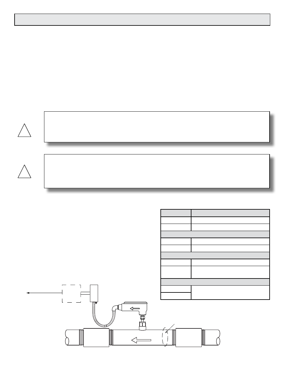
3.3.1 Signal and Power Wiring Connections
Built-in flow conditioner
Output signal(s)
to control system
Optional
ONICON
Display
FLOW
FLOW DIRECTION