How to determine the available straight pipe run – ONICON F-5200 Inline User Manual
Page 10
11451 Belcher Road South, Largo, FL 33773 • USA • Tel +1 (727) 447-6140 • Fax (727) 442-5699 • [email protected]
F-5200 Inline Thermal Mass Flow Meter Manual 05/14 - 0763-4 / 19476
Page
10
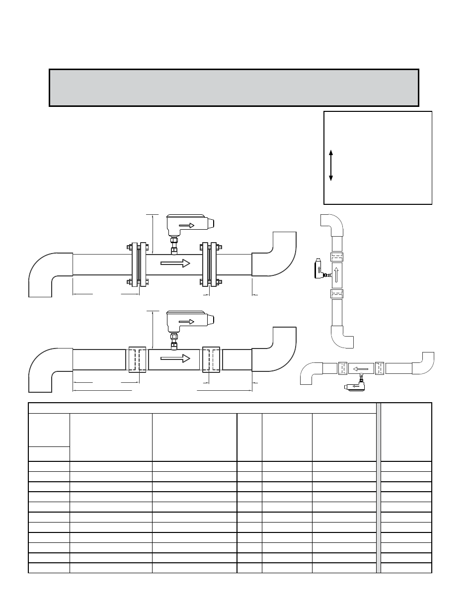
EVALUATING UPSTREAM
PIPING CONDITIONS
Straight Pipe
Single Bend
Pipe Reduction
Multiple Bends in Same Plane
Pipe Expansions
Tees
Multiple Bends Out of Plane
Modulating or Regulating Valve
W
orse
Better
In addition to the information provided on the previous page,
the diagrams and the table shown below should be used as a
guide to identifying the best installation location for the meter.
Required upstream/downstream distances in inches as
measured from the process connections.
9" Minimum
Height
Upstream
Downstream
Available Straight Run
Upstream
Downstream
9"Minimum Height
Meter may be installed in a
vertical pipe with upward or
downward flow
Meter may be installed on
the bottom of horizontal
pipes.
Flow
Flow
Flow
FLOW DIRECTION
FLOW DIRECTION
FLOW DIRECTION
Flow
FLOW DIRECTION
How to Determine the Available Straight Pipe Run:
Locate the longest straight unobstructed section of pipe available. To be unobstructed, the section of
pipe must be free of bends, tees, size transitions, valves or insertion probes of any kind.
3.
If there is insufficient straight run, allow 80% of the run upstream and 20% of
the run downstream. If the total length of straight run is less than 75% of the
recommended distance, performance may seriously degrade.
Minimum Straight Run required upstream of flow meter process connection based on the nature of the upstream obstruction.
Minimum
Downstream
Straight Run
Required After
Flow Meter
Process
Connection
Upstream
Obstructions
Single bend preceded by ≥
9 diameters of straight pipe
Or
Pipe size reduction in
straight pipe run
Multiple bends in plane with
< 9 diameters of straight
pipe between them
Or
Pipe size expansion in
straight pipe run
Tees
Multiple bends
out of plane
Modulating or
Regulating valves
Or
Roots or Diaphram
Utility Meters
Nom. Dia.
¼”
None
2.5”
2.5”
2.5”
2.5”
None
⅜”
1.25”
3.75”
3.75”
3.75”
3.75”
None
½”
1.5”
5”
5”
5”
5”
None
¾”
2.25”
7.5”
7.5”
7.5”
7.5”
1”
1”
3”
10”
10”
10”
10”
1”
1¼”
3.75”
12.5”
12.5”
12.5”
12.5”
2”
1½”
4.5”
15”
15”
15”
15”
2”
2”
6”
20”
20”
20”
20”
4”
2½”
7.5”
25”
25”
25”
25”
7”
3”
9”
30”
30”
30”
30”
9”
4”
12”
40”
40”
40”
40”
12”