Back, Left side, Back left side – Dynex DX-PDP42-09 User Manual
Page 6: Features
6
Features
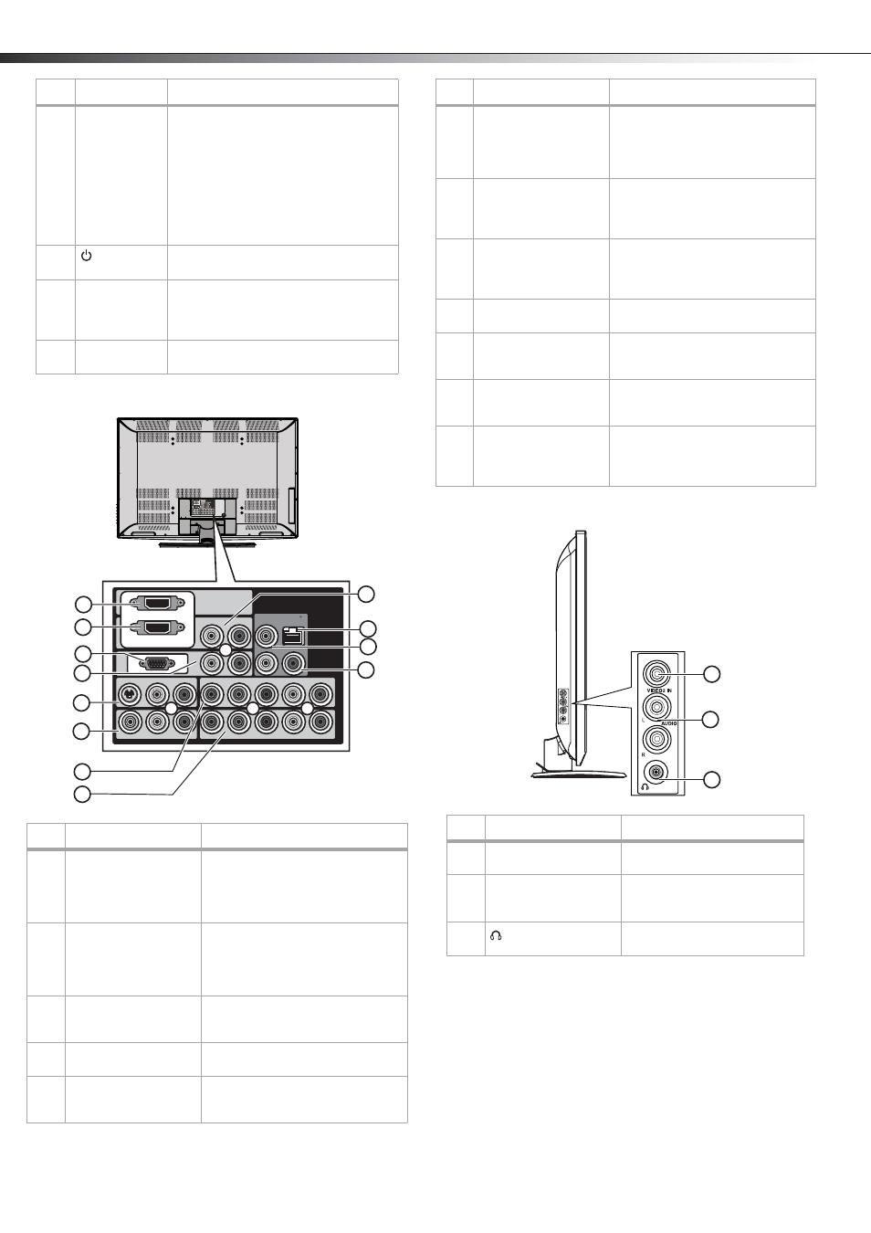
Back
Left side
4
INPUT button
Press to select the AV signal input. You
can select:
• TV (CABLE/AIR)
• VIDEO1 (REAR)
• S-VIDEO1 (REAR)
• VIDEO2 (SIDE))
• YPbPr1
• YPbPr2
• HDMI1 (REAR)
• HDMI2 (REAR)
• PC (VGA).
5
(power)
button
Press to turn your TV on or off.
6
Power/Standby
indicator
Lights when your TV is plugged into a
power outlet. When your TV is on, the
indicator is blue. When your TV is in
standby mode, the indicator is red.
7
IR sensor
Receives signals from the remote control.
Do not block.
#
Description
Function
1
HDMI 1 IN
Connect an HDMI cable to this
connector. Supports HD video and
digital audio. Does not support 480i.
Accepts DVI video using an adapter
or HDMI-to-DVI cable (not included).
2
HDMI 2 IN
Connect an HDMI cable to this
connector. Supports HD video and
digital audio. Does not support 480i.
Accepts DVI video using an adapter
or HDMI-to-DVI cable (not included).
3
PC IN VGA
Connect a VGA (D-sub) cable from
your PC to this connector (analog
PC).
4
PC IN AUDIO L/R
Connect left (white) and right (red)
audio cables to the L and R jacks.
5
S-VIDEO1 IN
(S-Video
and L/R audio)
Connect an S-Video cable and
connect left (white) and right (red)
audio cables to the L and R jacks.
#
Item
Description
Y
Y
Pb
Pr
Pb
Pr
L
R
R
L
PC IN
VIDEO
L
R
L
R
Y/C
R
L
R
R
L
HDMI 1 IN
HDMI 2 IN
DIGITAL-AUDIO
VIDEO
OUTPUT
N
I
1
r
P
b
P
Y
N
I
1
O
E
D
I
V
-
S
N
I
2
r
P
b
P
Y
N
I
1
O
E
D
I
V
L
VGA
11
9
10
1
2
3
5
8
7
4
6
12
6
VIDEO1 IN (composite
video and L/R audio)
Connect a video cable (analog
composite video - 480i) to this jack
(yellow).
Connect left (white) and right (red)
audio cables to the L and R jacks.
7
YPbPr1 IN, AUDIO L,
and AUDIO R
Connect component video cables to
the Y, Pb, and Pr jacks and audio left
(white) and right (red) cables to the L
and R jacks.
8
YPbPr2 IN, AUDIO L,
and AUDIO R
Connect component video cables to
the Y, Pb, and Pr jacks and audio left
(white) and right (red) cables to the L
and R jacks.
9
HDMI audio in
Connect left (white) and right (red)
audio cables to the L and R jacks.
10
Optical digital audio
output
Connect an optical cable from this
jack to the optical audio input jack of
a digital 5.1 audio system.
11
Composite video
output
Connect a video cable (yellow) to
this jack and to a VCR to record the
TV program.
12
Audio output
Connect left (white) and right (red)
audio cables from these L and R
jacks to the audio input jacks of a
stereo amplifier or receiver.
#
Description
Function
1
VIDEO2 IN (composite
video)
Connect analog composite
video (480i) to this jacks.
2
AUDIO IN (Audio L/R)
Connect the audio for
composite video or S-Video to
these jacks.
3
(Headphone jack)
Connect to an external
headphone for private listening.
#
Description
Function
1
2
3