Chapter 2 interfacing, Electrical power, Chapter 2 – NavCom RT-3020 Rev.A User Manual
Page 14: Interfacing
RT-3020S User Guide
3-12
Chapter 2
Interfacing
This chapter details the RT-3020
GPS
sensor
connectors and status display. Appropriate sources of
electrical power, and how to interface the
communication ports.
Electrical Power
The electrical power input comprises a 4-pin
LEMO
female connector located on the bottom front panel of
the RT-3020, and is labeled ‘DC PWR’ as shown in
Figure 2. The pin designations of this connector are as
follows; see Figure 2 for pin rotation.
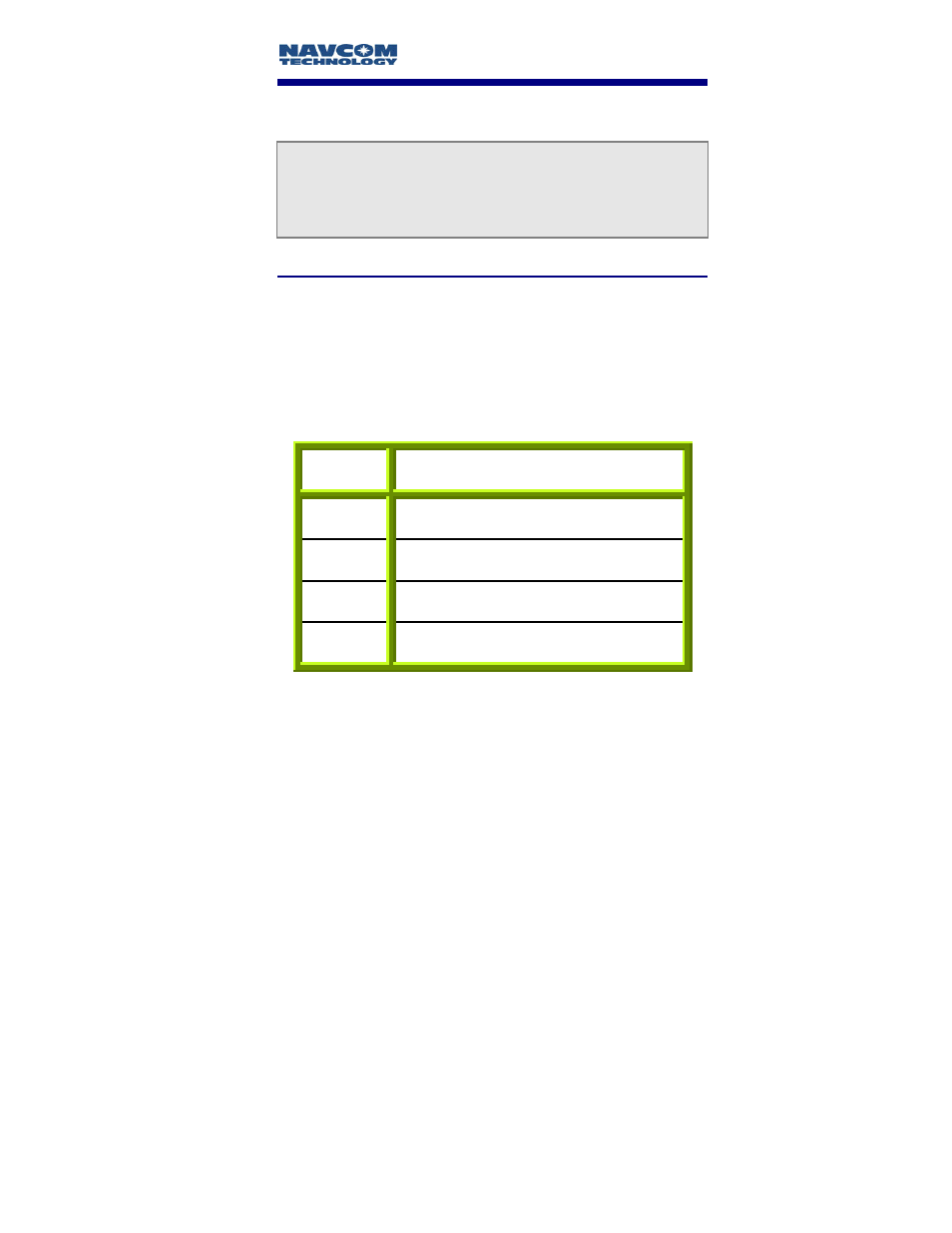
Pin Description
1 Return
2 Return
3
Power Input 10 to 30 VDC
4
Power Input 10 to 30 VDC
Table 1: External Power Cable Pin-Out
Pins 1 and 2 are connected together inside the RT-3020
GPS
sensor. Pins 3 and 4 are connected together inside
the
GPS
sensor.
This manual is related to the following products: