Installation (cont.) – MovinCool Office Pro W20 User Manual
Page 14
14
INSTALLATION (cont.)
Warning Signal Connection
(Output Signal Terminal L+ and L-)
The controller is equipped with a warning signal output relay type (Form C, normal
open dry contact) which can be used to monitor the failure conditions.
Relay contactor is closed when any of the following conditions has occurred:
a. Tank full
b. Temperature sensor fails
c. High pressure switch error
The relay output contactor is rated 2 A at 30 VDC or 2 A at 30 VAC (resistive load)
and it is compatible with various warning devices such as alarm speaker, light
indicators, etc.
Connecting Warning Signal From Controller
1. Remove service panel from the rear of the unit.
2. Squeeze the inner latches and push out the black cap from inside the panel.
3. Insert the warning signal wire through the hole in the rear panel.
Note: Use recommended warning signal wire size from 16 AWG to 26 AWG for a
solid wire, or 16 AWG to 22 AWG for a stranded wire with ring terminal for #6 stud
size.
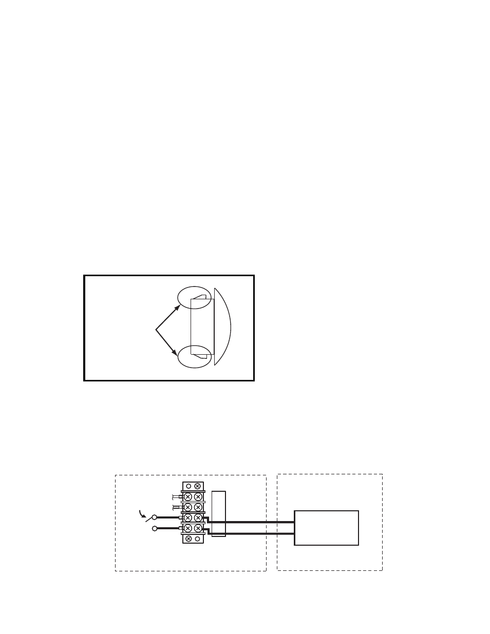
4. Connect the warning device to terminal L+ and L- according to its polarities.
ILL00046-00
Latch
Cap
E+
E-
L+
L-
UNIT TERMINAL
RELAY OUTPUT CONTACTOR
WARNING DEVICE
INPUT SIGNAL
ILL00047-00