Tuscany, Installing the gas line, Chimney liner installation – Montigo 34DVI Tuscany User Manual
Page 5
P/N XG0515
Page 5
Tuscany
Gas Fireplace Insert
Installation Section 1
nOTE:
After the gas line is connected, each appliance connection,
valve and valve train must be checked while under normal
operating pressure with either a liquid solution, or leak
detection device, to locate any source of leak. Tighten any
areas where bubbling appears or leak is detected until
bubbling stops completely or leak is no longer detected. Do
not use a flame of any kind to test for leaks.
Installing The Gas Line
Before installing the insert, ensure gas line is brought to close proximity
of the unit. For ease of installation, this appliance is equipped with an
approved flexible gas connector. The connector is factory-installed and
can be connected to the gas line as shown in figure 3.
DO nOT
cOnnEcT THE GAS LInE YET.
Note that the gas connection is on the right side of the unit.
Attach the gas line to the flexible gas connector with an approved fitting,
as required by the
applicable installation codes.
Only use gas shut-off valves approved for use by the state,
province, region, or governing body, in which the appliance
is being installed, or as required by the applicable installation
codes.
natural Gas
requires a minimum inlet gas supply pressure of 5.5"
W.C. & a manifold pressure of 3.5" W.C.
Propane Gas
requires a minimum inlet gas supply pressure of 11"
W.C. and a manifold pressure of 10" W.C. The fireplace gas connection
and the main operating gas control valve is located underneath the
firebox in the control compartment.
The appliance and its individual shutoff valve must be disconnected
from the gas supply piping system during any pressure testing of that
system at test pressures in excess of 1/2 psig (3.5 kPa)
The appliance must be isolated from the gas supply piping system by
closing its individual manual shutoff valve during any pressure testing
of the gas supply piping system at test pressures equal to or less than
1/2 psig (3.5 kPa)
Figure 3. Gas line location on the right-hand side of the appliance
(similar on both sides)
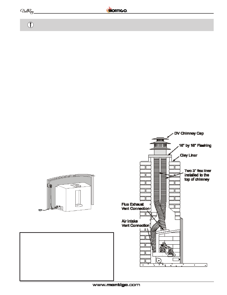
chimney Liner Installation
This appliance is approved for installation only with DelRay's Direct
Vent flex liner kit (part# VT35DV3). The kit contains two 3" diameter
flex liners, a Direct Vent chimney cap, and a 16" by 16" flashing.
All installations must conform with local codes. In the absence of local
codes, installations must conform with the most recent version of the
American National Fuel Gas Code
(AnSI Z223.1-1988)
or the
Canadian Gas Installation Code (
cAn/cGA B149.1 and .2)
.
STEP 1:
Determine the length of the vent run in the masonry
chimney. Measure from the masonry base of the fireplace
to the top of the clay liner and allow an extra 18" for fitting
to the fireplace.
STEP 2:
Stretch the flex liner to the desired length. Or, if necessary,
cut the flex liner to the measured length using snips, a
hacksaw, or a disc cutter. Remember to
allow an extra
18" for fitting
to the fireplace.
Note: Mark one of the pipes for air intake and one for exhaust
outlet, to ensure that the proper connections will be made.
Figure 4: Direct Vent System