Montigo E36DV-TV User Manual
Page 5
0 9 / 9 6
Page 5 of 14
E36DV-TV
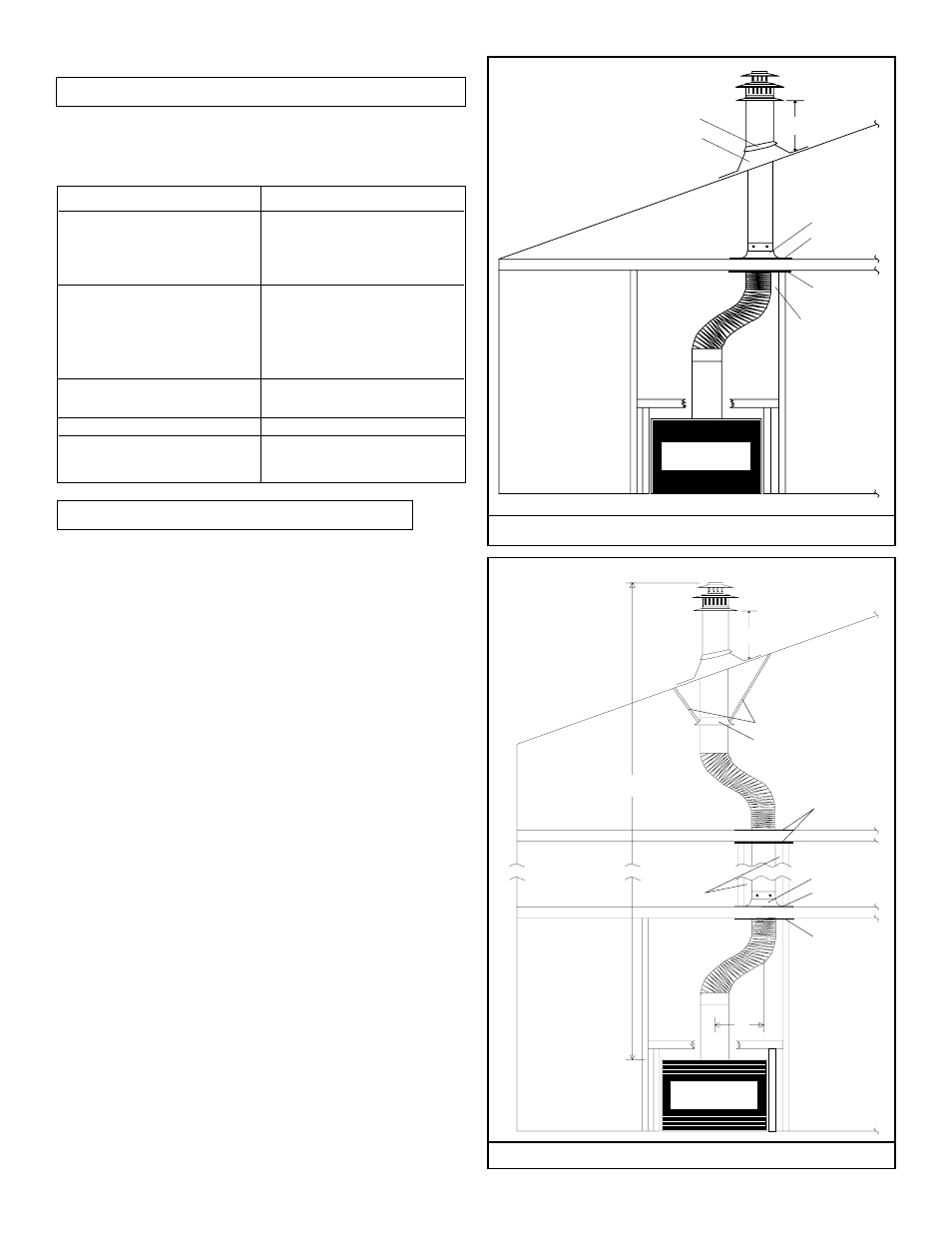
2 Feet
Support ring
Support plate
Storm collar
Roof flashing
Firestop
Minimum 1"
clearance to all
combustibles
materials
FIGURE 9A.
Support ring
Support straps
Firestop
Support ring
Support plate
Firestop
20 Feet
2'
FIGURE 9B.
2 Feet
Minimum 1"
clearance to all
combustibles
materials
A complete Econo Plus 36DV-TV vertical vent installation may
comprise of the following components:
A - Termination
MVTK-1
B - Flex sections
MFL-1 (1' 6" section)
MFL-2 (2' 6" section)
MFL-3 (3' 6" section)
MFL-4 (4' 6" section)
C - Solid sections
MEXT-1 (1' section)
MEXT-2 (2' section)
MEXT-3 (3' section)
MEXT-4 (4' section)
MEXT-6 (6' Section)
D - Support Ring & Plate
MSPXT-7 (7" Support
Plate & Ring)
E - 7" Firestop
FS-7 (7" Firestop)
F - Roof Flashing
MRF-16 (1/12 to 6/12 pitch)
MRF-12 (6/12 to 12/12 pitch)
VERTICAL DIRECT VENT TERMINALS
Shall not be installed;
- Less than two feet above the highest point where vent
passes through the roof.
- Less than six feet from a mechanical air inlet.
- Less than three feet from a parapet wall.
Offsets;
- A maximum of two offsets with 90 degree bends may
be made and shall not exceed total length of 25% of
the vertical vent height, when measured center to
center of piping.
EXAMPLE:
Typical vent installaion
(see figure 2)
20' vertical vent
2 - 2' offsets required
25% of 20' = 4' max. offset allowed
this venting system complies to
instruction requirements.
- Maximum vent height is 28 feet above fireplace.
- Minimum clearances 1" from vent to all combustible
materials must be maintained.
INSTALLATION OF VERTICAL DIRECT VENT