Section 3-2-1: venting layout, Pvtk-1), Installation – Montigo P42DF User Manual
Page 10
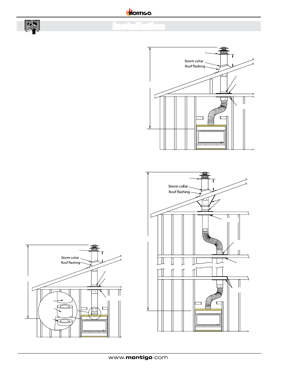
Figure 9. Top vent, Roof mounted termination with no offset in vent run.
Figure 9a. Top vent, Roof mounted with 1 offset (1 offset= two 90°
bends).
Figure 9b. Top vent, Roof mounted with 2 offsets (1 offset= two 90°
bends).
Roof mounted Terminations
The following details are some possible configurations for Roof mounted
terminations.
Support ring
Support plate
Firestop
32’ max.
2’ min.
PVTK1
Termination
Support ring
Support plate
Firestop
32’ max.
2’ min.
Obstacle
PVTK1
Termination
Section 3-2: Installing a Roof Mounted Direct
Vent Termination (PVTK-1)
This section applies to installations where the direct vent termi-
nation will be roof mounted.
Section 3-2-1: Venting Layout
Selection of components and details of venting lay out should
adhere to the following guidelines:
The maximum termination point is 32’ above the fireplace (NOTE:
if the maximum termination height is used, the flame pattern
may be affected).
The Vertical termination must be a minimum 2’ higher than where
the termination exits the roofing materials, (asphalt shingles,
cedar shakes, etc). This distance should be measured from the
high side of the roof slope where the flue flashing intersects the
roofing materials. (see Figures 9 to 9c).
Termination location must be a minimum 6’ from a mechanical
air inlet.
For a more detailed diagram of allowed termination locations,
see Appendix A.
A maximum of two offsets (each offset is made up of 2-90°
bends) may be made for vertical vent runs.
Firestops must be installed as required by National & local codes
Ensure all horizontal runs are supported with a minimum of 3
supports per 10’ of venting.
Install all roof flashing and storm collars as shown.
Support straps or
support plate & ring
2’ min.
Firestop
Firestop
Firestop
32’ max
Support plate
& ring
Obstacle
PVTK1
Termination
PEXT
PXT-10
Adaptor
Flue
Collar
Page 10
P42DF* Indoor Gas Fireplace
XG0195 - 150204.2
Installation