Main p.c. board connections – MK Products Cobramatic 120 VAC V6 User Manual
Page 21
Cobramatic
®
Owner’s Manual - page 13
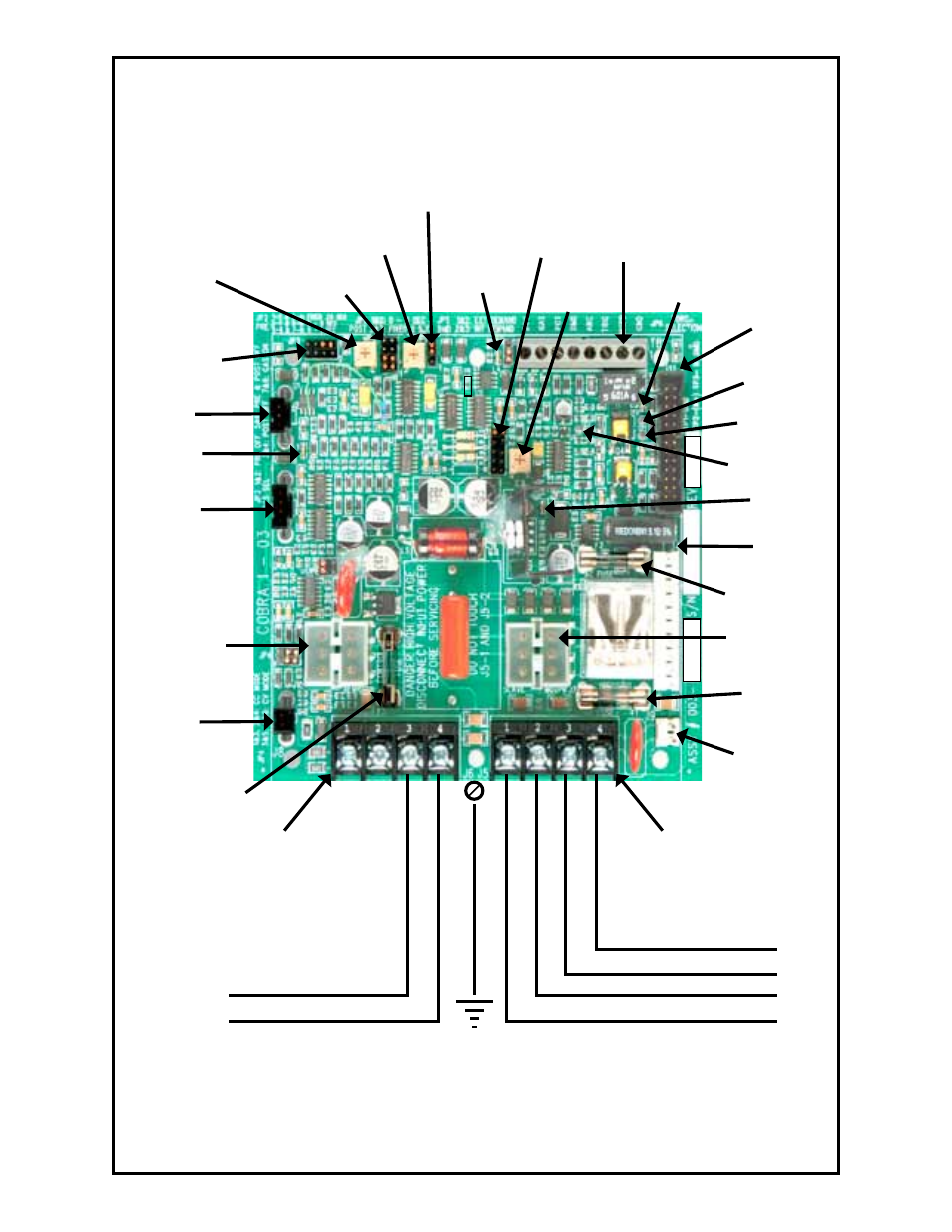
Main P.C. Board Connections
JP3
Gas Purge Jumper
P1
Pre-Purge Trim Pot
P2
Post-Purge Trim Pot
J11
Front Panel
J4
Front Panel
J9
Brake Solenoid
J7
Slave Motor
J10
Transformer
J8
Current Sensor
J1
Trigger Normal/Latch
J2
Gas Solenoid
J5
Terminal Strip
J6
Terminal Strip
TB1
Remote
Input/Output
TP2
Test Point - MTR VDC
L1
Gas “on” (yellow)
L4
Posa Start “on”
(blue)
L3
Trigger “on”
(green)
L2
Contactor Signal
“on” (red)
TP1
Test Point - GROUND
F2
Line Fuse
JP2
Adj. Gas Purge Jumper
JP1
Adj. Gas Purge Jumper
Chassis
Ground
(Green)
Opt. Contactor - 115 VAC Out - Hot - Black
Input Power - 115 VAC - Hot - Black
Opt. Contactor - 115 VAC Out - Neutral - White
Input Power - 115 VAC Neutral - White
Closing Contacts Out
Closing Contacts Out
TP3
Motor Demand
P3
Motor Gain
F1
Line Fuse
F3
Motor Fuse
JP6
Torch Select
- CobraTig 150 XM (32 pages)
- CobraCooler (20 pages)
- Advanced Color Logic Rev.A (55 pages)
- Advanced Color Logic Rev.A (55 pages)
- DiamondBack Weldhead (30 pages)
- MiniMicro Orbital Weldhead (30 pages)
- Copperhead Weldhead (42 pages)
- Python Gun (37 pages)
- Python MM Com ACWC (43 pages)
- MK Cobramatic Pro Series (43 pages)
- CobraMAX (28 pages)
- Cobra SX (28 pages)
- Cobra MX (41 pages)
- Prince XL Spool Gun (41 pages)
- Prince XL LE Com ACWC (41 pages)
- Prince SG (30 pages)
- WC-1-110 (26 pages)
- MK200 (20 pages)
- Sidewinder (26 pages)
- Weld Control (45 pages)
- Python LX Euro (41 pages)
- Python LX LE Com ACWC (41 pages)
- Prince XL Fronius Com ACWC (39 pages)
- Cobra SX Fronius Com AC (30 pages)
- Cobra MX MM Com ACWC (41 pages)
- Cobra SX MM Com AC only (30 pages)
- Positioner 1/AirCrafter T-25 (17 pages)
- Prince XL MM Com ACWC (39 pages)
- CobraTurn Digital Turntable (23 pages)
- CobraCooler 2003 (15 pages)
- CobraCooler 2005 (14 pages)
- Cobramatic II (45 pages)
- Cobramatic 120VAC (47 pages)
- Cobramatic 42VAC (38 pages)
- CobraMig 260 PS/Feeder (62 pages)
- Cobra System III Gooseneck (26 pages)
- Prince XL/Spool Gun (41 pages)
- Cobra Gold Gooseneck (41 pages)
- RoboKing (33 pages)
- Python Rev.D (40 pages)
- Cobra MX Gun - ACWC (36 pages)
- Positioner #3 (14 pages)
- Positioner #2 (15 pages)
- MK 2000A (29 pages)