MK Products Cobramatic 120 VAC V6 User Manual
Page 12
Cobramatic
®
Owner’s Manual - page 4
Coolant Inlet (For Liquid Cooled Guns)
Front panel access to connect the coolant hose to the middle fitting on the
power block.
Work Cable (Ground)
Connect a work lead of sufficient size and length between the proper output
stud on the power source and the work. Be sure the connection to the work
ground makes tight metal to metal electrical contact. Improper work lead
connections can result in poor arc initiation, and unsatisfactory weld results.
Consult welding power supply manufacturer for proper work lead size.
Section B
Operation
General
The AC slave motor in the feeder runs at a fast, constant speed, but has very
low torque. It is always trying to feed more wire than the gun motor wants,
and when the gun motor gets all the wire it wants, the slave motor automati-
cally slows, preventing a bird’s nest. Because of the low torque produced
by the slave motor, a combination drag and electric brake system is used to
prevent wire overrun rather than relying on spindle tension alone. The spool
drag tension is produced by the patented Wire Retainer Bar mechanism to
keep the wire slightly taut. The 24 VDC gun “pull” motor is controlled by a
solid state speed control in the cabinet and through a potentiometer located
in the gun.
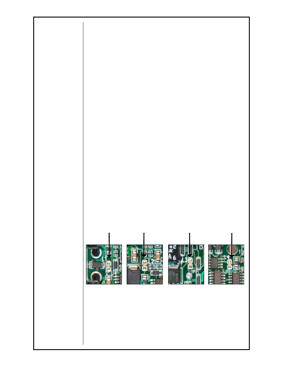
The normal operating sequence of the wire feeder can be viewed on the
board itself via sequence LED’s. When the system is triggered, the green
Trigger LED (L3) and the yellow Gas Solenoid LED (L1) illuminate simultane-
ously. The red Contactor/Wire Feed LED (L2) illuminates after the prepurge
time. The blue Arc On LED (LED) illuminates as the arc is established. When
the trigger is released the normal LED operating sequence is blue, green and
red (L4, L3, & L2) turn off simultaneously followed by the yellow (L1) after the
postpurge time has elasped (Figure 4).
Recommended Processes and Equipment
The Cobramatic
®
feeder is recommended for use with GMAW and FCAW
welding applications. It is recommended for use with constant voltage power
sources but will also work with CC machines. The Cobramatic
®
feeder is
capable of feeding wires (diameter capacity) ranging from .030” through
.045” solid/cored and .030” through 1/16” aluminum.
Figure 4 - L1, L2 & L3
Blue LED
when arc established
L4
Yellow LED
when solenoid
opens.
L1
Red LED when
wire feeds/
contactor closes.
L2
Green LED
when triggered.
L3
For reference, see Main P.C. Board Connections picture in Section F