Testing the gun – MK Products Cobramatic 120 VAC V6 User Manual
Page 17
Cobramatic
®
Owner’s Manual - page 9
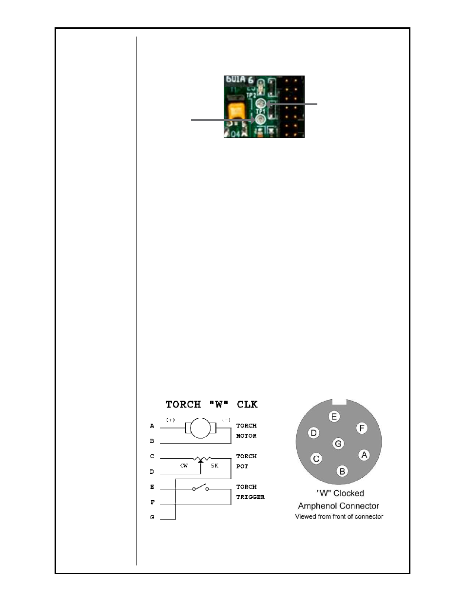
To test the motor voltage circuit and measure how much voltage is being
delivered to the gun motor, place a voltmeter across diode test points
TP1
& TP2 and depress gun trigger. A reading between 0 - 30 VDC should be
observed, as the gun potentiometer is varied.
Testing the Gun
Motor Check
Remove the amphenol connector from the cabinet.
Using the gun amphenol, check the resistance across pins
“A” and “B”
(motor leads). The resistance across the motor should be between
5-10
ohms.
If an open circuit or short exists, check the motor leads and motor indepen-
dently.
Testing the Potentiometer - “W” Clocked Amphenol Connector
Using the gun amphenol, check the resistance across pin
“D” (wiper) and
pin
“C”. The resistance should vary from 0 - 5K ohms as you turn pot..
Check the resistance across pin
“D” (wiper) and pin “G”. The resistance
should vary from
5K - 0 ohms as you turn pot.
Testing the Micro Switch
Using the gun amphenol, check for continuity across pins
“E” and “F” when
the trigger is pressed.
Figure 9
For reference, see Main P.C. Board Connections picture in Section F
Motor Voltage
Test Point
TP2
Motor Voltage
Test Point
TP1