Posa start operating procedure – MK Products Cobramatic 120 VAC V6 User Manual
Page 14
Cobramatic
®
Owner’s Manual - page 6
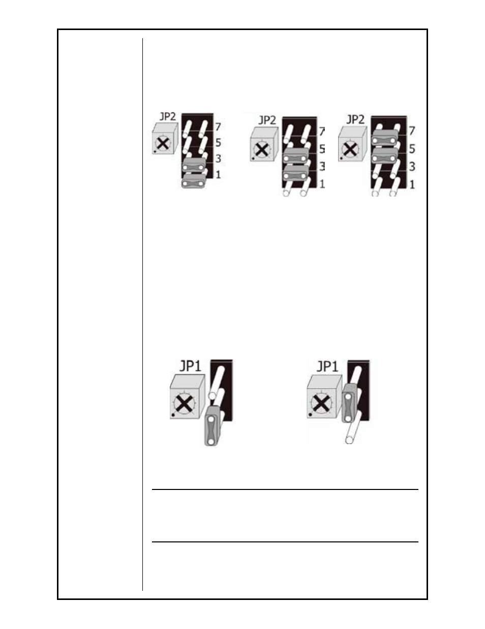
across rows 3 & 5. For the 0-5 second range, move the jumpers across rows
5 & 7 (Figure 6a).
Timing adjustment for the variable settings are as follows: Move the jumpers
to either variable setting location. Turn potentiometer screw (Small flat or
cross-head) half way. Pull gun trigger and count time between red contactor
wire feed LED (L2) and yellow Gas Solenoid LED (L1). Adjust pot screw as
necessary.
Figure 6a
Post-Purge Settings & Adjustments (JP1)
The Post-Purge Jumper/Pot Configuration at JP1 has 2 available settings: 2
sec. fixed and variable from 0-5 seconds.
By default, the two-pin jumper across the top-and-middle pins, is configured
for 2 sec. Just to the left of the jumper is a ¾-turn pot which is used with the
variable setting. For the 0-5 second range, move the jumper from the top-
and-middle to the middle-and-bottom pins (Figure 6b).
Timing adjustment for the variable settings are as follows: Move the jumpers
to variable setting location. Turn potentiometer screw (Small flat or cross-
head) half way. Upon release of gun trigger, count time between yellow Gas
Solenoid LED (L1) and green Trigger LED (L3). Adjust as necessary.
Posa Start Operating Procedure
CAUTION:
Do not operate this wire feeder on a power source having a high-fre-
quency (HF) starting circuit until the high frequency feature has been
turned off or disabled. Failure to disable the HF will result in damage
to the PosaStart circuitry of the main board.
General
The Posa Start Run-in Speed Control, located on the front panel, provides
adjustment for slow wire run-in. Once the arc has been established, the wire
feed speed is automatically changed from the slow run-in speed to the weld-
ing speed set on the gun potentiometer.
Rows 1 & 3: 0.25 sec. fixed Rows 3 & 5: 0-1 sec.
Rows 5 & 7: 0-5 sec.
Middle/Bottom: 0-5 sec.
Top/Middle: 2 sec fixed
Figure 6b