Welding gun connections – MK Products Cobramatic 120 VAC V6 User Manual
Page 11
Cobramatic
®
Owner’s Manual - page 3
Wire Threading Procedure
Place wire size selector switch on front panel to the correct position for the
wire being used.
Loosen end of wire from spool and cut off any kinked or bent portions.
Unreel and straighten out first 6” to 8” of wire.
Raise wire type lever on the slave motor assembly of feeder to center posi-
tion.
Route wire into inlet guide, along drive roll groove, and into wire conduit.
Flip wire type lever to display name of wire type being used.
Proper tension is achieved when wire does not slip if a small amount of pres-
sure is added to the wire between thumb and forefinger as wire exits the tip.
Adjust gun idler arm tension screw as necessary.
Wire Retainer Bar
The design of the patented Cobramatic
®
Wire Retainer Bar performs two very
important and very basic functions of the wire feeder: a) spool drag tension,
and b) wire maintenance on the spool.
The spool drag tension is set by lowering the wire retainer bar onto the
wire inside of the spool. The spring tension of the wire retainer bar applies
enough pressure on the spool so that when the gun trigger is released,
engaging the brake pall, the spool does not overrun kicking wire off the spool.
Wire maintenance on the spool is performed by the applied pressure of the
surface of the wire retainer bar spread across the coiled wire on the spool.
The replaceable pad of the wire retainer bar is designed to hold the wire on
the spool, maintaining the smooth layering of the wire and keeping it from
jumping off, and possibly electrically shorting to the cabinet chassis.
Welding Gun Connections
Control Cable
The 7-Pin “W” Clocked connector screws onto the mating receptacle on the
front panel of the wire feeder. This provides all electrical signals (motor volt-
age, potentiometer control & trigger) to and from the feeder to the gun.
Wire Conduit Inlet
Front panel access to attach conduit to front of slave motor assembly.
Power Cable Inlet
Front panel access to attach power cable (air or water) to top of power block.
Guns with ring lugs, MUST connect to top bolt of power block.
Gas Inlet
Front panel access to attach gas hose to bottom fitting of power block.
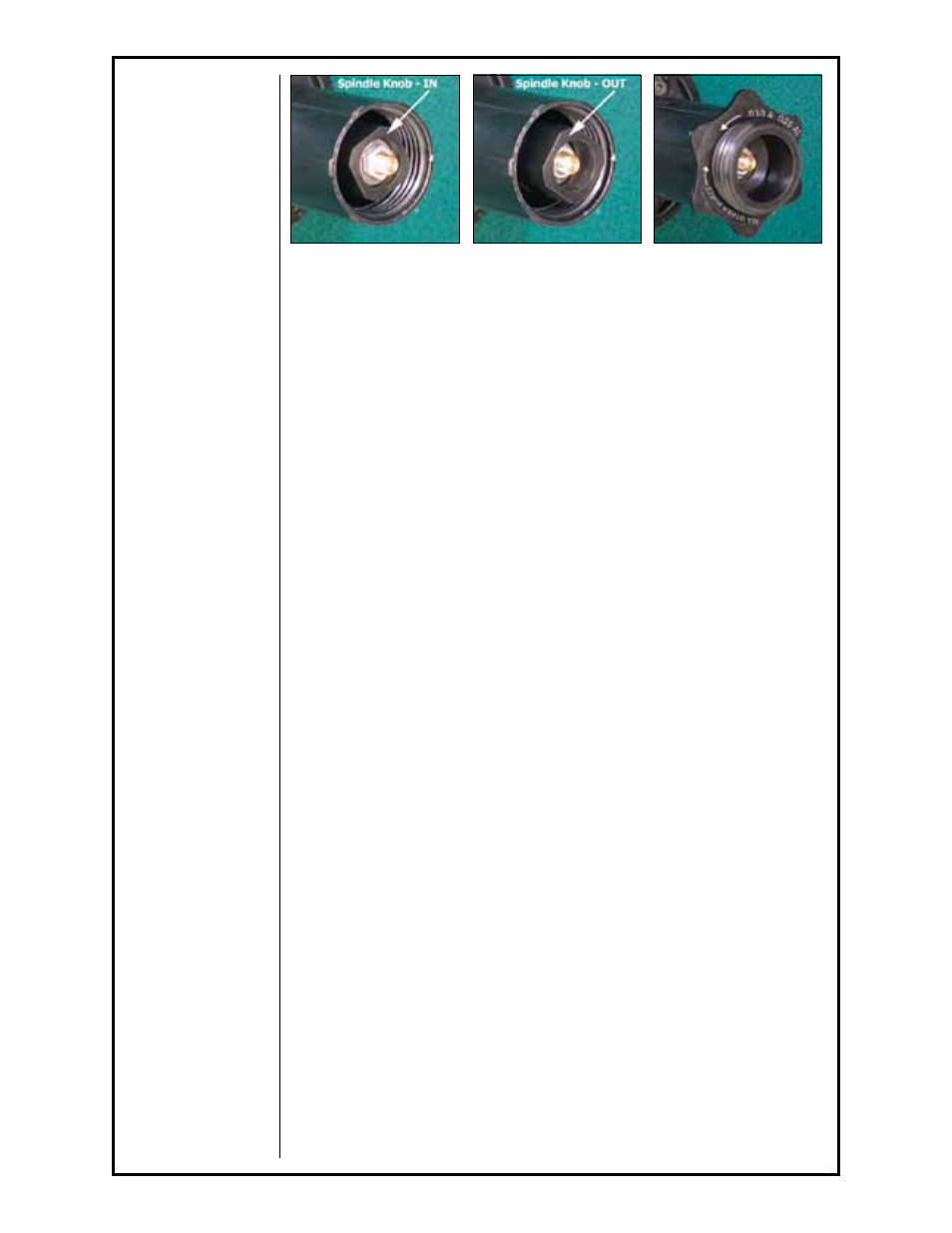
IN - All other wires
Figure 1
OUT - .030/.035
Aluminum ONLY
Figure 2
Wire Spool Retainer In "Tool
Mode"; used to change
spindle drag.
Figure 3