Connecting to the console port, Wiring map for serial cable, Table 5 – Microsens MS453490M Installation User Manual
Page 39: Serial cable wiring, Figure 13, Console cable, Onnecting, Onsole
C
HAPTER
3
| Installing the Switch
Connecting to the Console Port
– 39 –
C
ONNECTING
TO
THE
C
ONSOLE
P
ORT
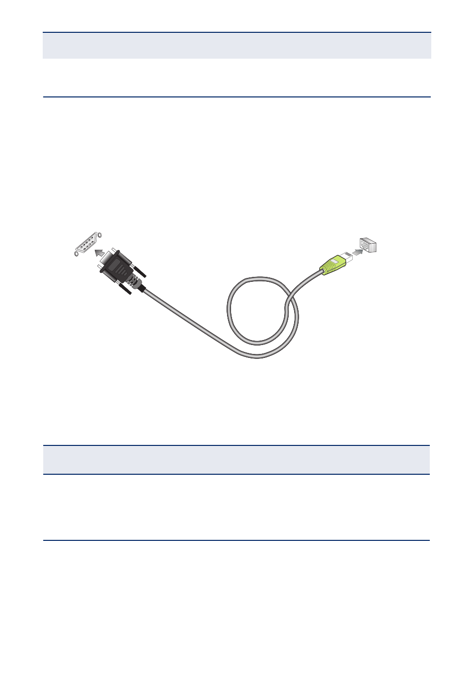
This port is used to connect a console device to the switch through a serial cable.
The console device can be a PC or workstation running a VT-100 terminal
emulator, or a VT-100 terminal. A crossover RJ-45 to DB-9 cable is supplied with
the unit for connecting to the console port, as illustrated below. The PIN
assignments used to connect to the serial port are described below.
Figure 13: Console Cable
W
IRING
M
AP
FOR
S
ERIAL
C
ABLE
The serial port’s configuration requirements are as follows:
◆
Default Baud rate—115,200 bps
◆
Character Size—8 Characters
Table 5: Serial Cable Wiring
Switches 8-PIN Serial
Port
Null Modem
PC’s 9-PIN DTE Port
6 RXD (receive data)
<-----------------------
3 TXD (transmit data)
3 TXD (transmit data)
------------------------>
2 RXD (receive data)
5 SGND
(signal ground)
--------------------------
5 SGND (signal ground)
RJ-45 Connector
Console Port
DB-9 Port
aaa
aaa
aaa
aaa
aaa
aaa