Denso BHT-400B-CE User Manual
Page 143
Chapter 3 Communications Operations of the BHT
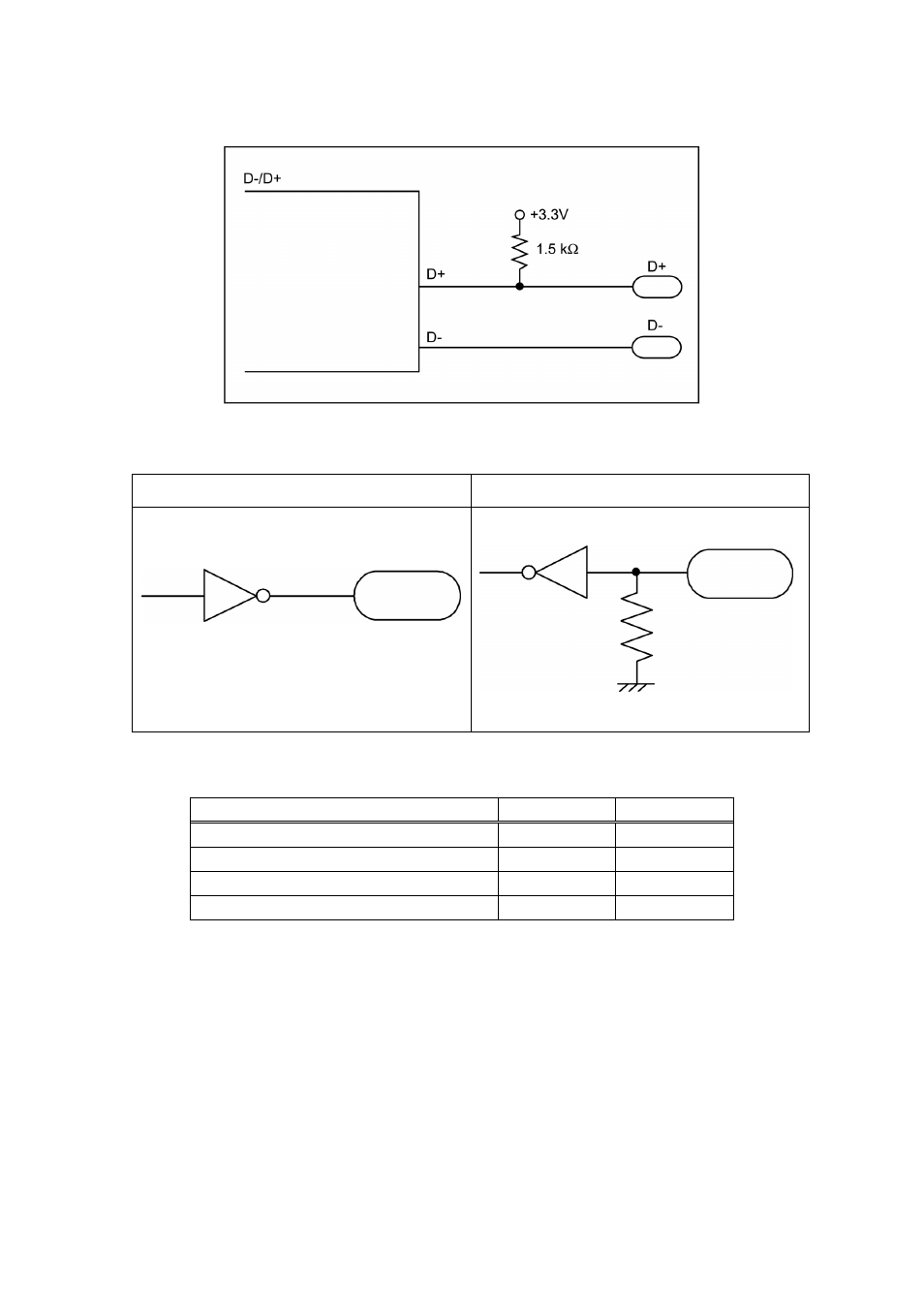
(3)-1 Interface circuit (USB)
USB Driver/Receiver
(3)-2 Interface circuit (RS-232C)
Output circuit
Input circuit
TxD, RTS
RxD, CTS
5k
Ω
Signal Level
Item Min.
Max.
Output voltage “H” (3K
Ω load)
5V
15V
Output voltage “L” (3K
Ω load)
-15V
-5V
Input voltage “H”
3V
15V
Input voltage “L”
-15V
-3V
(Note 1) Input / Output voltages are specified at the terminal of the interface connector.
(Note 2) Output voltage becomes unsettled when the connector communication device file is
closed.
(Note 3) Output voltage shall be under the following conditions:
Power voltage: Rated voltage
Load resistance: 3 k
Ω
123
This manual is related to the following products: