Introducing the pc-card-dac08, Overview: pc-card-dac08 features, Pc-card-dac08 block diagram – Measurement Computing PC-CARD-DAC08 User Manual
Page 8: Software features
Chapter 1
Introducing the PC-CARD-DAC08
Overview: PC-CARD-DAC08 features
The PC-CARD-DAC08 is an eight-channel, analog output control board for IBM PC compatible computers
having PCMCIA-type slots. The heart of the board is an octal, 13-bit digital-to-analog converter, of which only
12 bits are used for each output. Analog voltage signals are generated by the D/A from registers. Control of I/O
operations is done by the Field Programmable Gate Array (FPGA) on the board (
). Double-buffering of
the output registers permits simultaneous output changes.
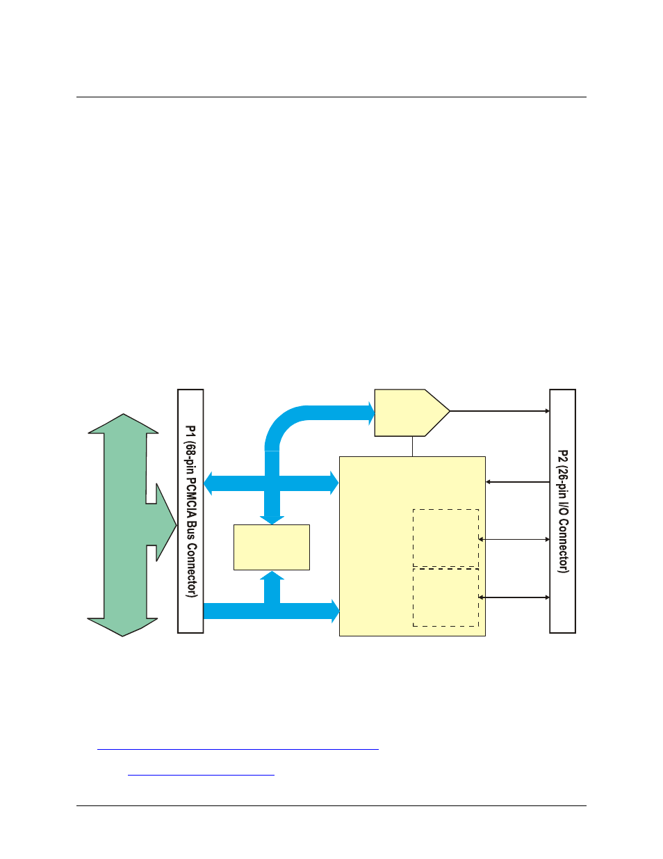
Figure 1. PC-CARD-DAC08 block diagram
The analog output range is bipolar, ±5V.
The PC-CARD-DAC08 also provides eight bi-directional digital I/O lines arranged in two 4-bit ports. The DIO
lines provide the capability of sensing and controlling discrete events (via external signal-conditioning
hardware). You can configure the digital ports as eight inputs, eight outputs, or four inputs and four outputs.
PC-CARD-DAC08 block diagram
PC-CARD-DAC08 functions are illustrated in the block diagram shown here.
Controller
FPGA
H
o
s
t Bu
s
Ad
a
p
to
r
DIO 7:4
DIO 3:0
Address Bus
Digital
I/O Port
4-bits
Digital
I/O Port
4-bits
EXT INT
D/A out 7:0
OCTAL D/A
converter
13-bit
Attribute
Memory
Data Bus
Software features
For information on the features of InstaCal and the other software included with your PC-CARD-DAC08, refer
to the Quick Start Guide that shipped with your device. The Quick Start Guide is also available in PDF at
.
8