Measurement Computing PC-CARD-DAC08 User Manual
Page 18
PC-CARD-DAC08 User's Guide
Specifications
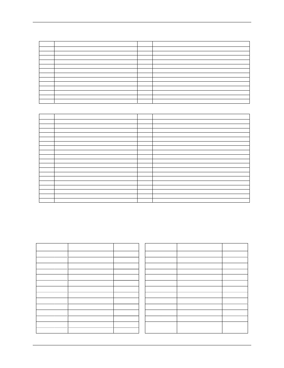
Table 9. Connector pin out
Pin
Signal Name
Pin
Signal Name
1
GND
14
EXTERNAL INTERRUPT IN
2
DIGITAL I/O 0
15
DIGITAL I/O 1
3
DIGITAL I/O 2
16
DIGITAL I/O 3
4
DIGITAL I/O 4
17
DIGITAL I/O 5
5
DIGITAL I/O 6
18
DIGITAL I/O 7
6
PC +5V OUT
19
D/A OUT 0
7
GND
20
D/A OUT 1
8
GND
21
D/A OUT 2
9
GND
22
D/A OUT 3
10
GND
23
D/A OUT 4
11
GND
24
D/A OUT 5
12
GND
25
D/A OUT 6
13
GND
26
D/A OUT 7
Table 10. PC-CARD-C37F/26 user connections on 37D
Pin
Signal Name
Pin
Signal Name
1
GND
20
D/A OUT 1
2
EXTERNAL INTERRUPT IN
21
GND
3
GND
22
D/A OUT 2
4
DIGITAL I/O 0
23
GND
5
DIGITAL I/O 1
24
D/A OUT 3
6
DIGITAL I/O 2
25
GND
7
DIGITAL I/O 3
26
D/A OUT 4
8
DIGITAL I/O 4
27
GND
9
DIGITAL I/O 5
28
D/A OUT 5
10
DIGITAL I/O 6
29
GND
11
DIGITAL I/O 7
30
D/A OUT 6
12 GND
31 GND
13
GND
32
D/A OUT 7
14
PC +5V OUT
33
GND
15 GND
34 N/C
16 GND
35 N/C
17 GND
36 N/C
18
D/A OUT 0
37
N/C
19 GND
Note 1:
Pins 19, 21, 23, 25, 27, 31, and 33 connect to pin 1 inside the 37D housing.
If you remove the 37-pin connector (P2) from the PC-CARD-C37F/26 cable assembly and replace it with a
different user connector, make sure that the wiring of the replacement connector adheres to the twisted-pair
wire pairings listed in the following table.
Table 11. Wire run list C3726 — P1 (Honda) to P2 (37D)
P1 (Honda)
Twisted pair wire
P2 (37D)
P1 (Honda)
Twisted pair wire
P2 (37D)
1 BLK
1 11
BLK
16
20 BLU
20 17 RED
9
2 RED
4 12
YEL
29
8 BLU
3
15
RED
5
3 BLK
6 13
BLK
17
16 GRN
7 22 YEL
24
4 WHT
8 14
ORN
2
5 BLK
10
21
RED
22
6 GRN
14
23
RED
26
25 RED
30 18 WHT
11
7 BLK
12
19
RED
18
26 ORN
32 24 BRN
28
9 BLK
13
10 BRN
15
_ SHIELD 33
18