Connecting the board for i/o operations, Connectors, cables – main i/o connector, Pin out – main i/o connector – Measurement Computing PC-CARD-DAC08 User Manual
Page 11
PC-CARD-DAC08 User's Guide
Installing the PC-CARD-DAC08
Connecting the board for I/O operations
Connectors, cables – main I/O connector
The table below lists the board connector, applicable cables, and compatible accessory products.
Board connector, cables, and accessory equipment
Connector type
Honda 26-pin mini D-type
Connector compatibility
Translates to 37D pin out using PC-CARD-C37F/26
Compatible accessory products
CIO-MINI37
SCB-37
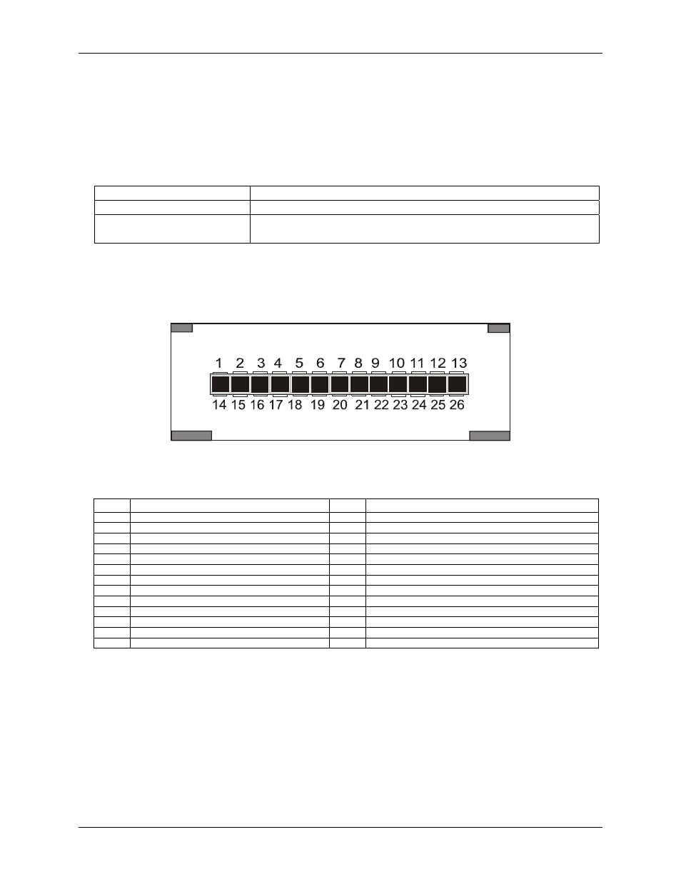
Pin out – main I/O connector
Figure 2. 26-pin I/O mini-connector
shows a PC-CARD-DAC08 case looking into the male mini-connector. The connector is mechanically
keyed to insure that the cable is inserted correctly.
26-pin mini-connector pin out
Pin
Signal Name
Pin
Signal Name
1
GND
14
EXTERNAL INTERRUPT IN
2
DIGITAL I/O 0
15
DIGITAL I/O 1
3
DIGITAL I/O 2
16
DIGITAL I/O 3
4
DIGITAL I/O 4
17
DIGITAL I/O 5
5
DIGITAL I/O 6
18
DIGITAL I/O 7
6
PC +5V OUT
19
D/A OUT 0
7
GND
20
D/A OUT 1
8
GND
21
D/A OUT 2
9
GND
22
D/A OUT 3
10
GND
23
D/A OUT 4
11
GND
24
D/A OUT 5
12
GND
25
D/A OUT 6
13
GND
26
D/A OUT 7
Connect the analog devices that you want to control with the high side to the numbered analog output, and the
low side to an adjacent ground (GND).
11