Digital input / output, Power consumption, Environmental – Measurement Computing PC-CARD-DAC08 User Manual
Page 17: Mechanical, Connector and pin out
PC-CARD-DAC08 User's Guide
Specifications
Typical accuracy is derived directly from the various component typical errors. This typical error calculation
for a SW calibrated PC-CARD-DAC08 yields ±1.8 LSB. However, this again assumes that each of the errors
contributes in the same direction and the ±1.8 LSB specification is quite conservative.
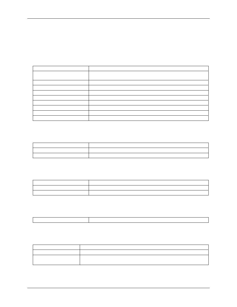
Digital input / output
Table 4. DIO specifications
Digital type
FPGA
Configuration
Two ports, four bits each. Programmable as eight input, eight output, or four input
and four output
Input low voltage
0.8 V max
Input high voltage
2.0 V min
Output low voltage (IOL = 4 mA)
0.23 V max
Output high voltage (IOH = –4 mA)
3.86 V min
Absolute maximum input voltage
–0.5 V , +5.5 V
Power-up / reset state
Input mode (high impedance)
Interrupt enable
Programmable
Interrupt source
External (EXTERNAL INTERRUPT), falling edge triggered
Power consumption
Table 5. Power consumption specifications
+5 V quiescent
Normal operation
42 mA typical, 110 mA max
CIS read
57 mA typical, 135 mA max
Environmental
Table 6. Environmental specifications
Operating temperature range
0 to 70 °C
Storage temperature range
-40 to 100 °C
Humidity
0 to 95% non-condensing
Mechanical
Table 7. Mechanical specifications
Card dimensions
PCMCIA type II: 85.6 mm (L) x 54.0 mm (W) x 5.0 mm (H)
Connector and pin out
Table 8. Connector specifications
Connector type
Honda 26-pin mini D-type
Connector compatibility
Translates to 37D pin out using PC-CARD-C37F/26
Compatible accessory
products
CIO-MINI37
SCB-37
17