Measurement Computing USB-4301 User Manual
Page 14
USB-4301 User's Guide
Functional Details
14
2
9
IN
P
3
3
0
G
A
T
3
3
1
O
U
T
3
3
2
IN
P
4
3
3
G
A
T
4
3
4
O
U
T
4
3
5
IN
P
5
3
6
G
A
T
5
3
7
O
U
T
5
3
8
G
N
D
3
9
4
0
4
1
4
2
4
3
4
4
4
5
4
6
4
7
5
0
D
O1
5
1
D
O2
5
2
D
O3
5
3
D
O4
5
4
D
O5
5
5
D
O6
5
6
D
O7
4
8
G
N
D
4
9
D
O0
R
S
V
D
R
S
V
D
R
S
V
D
R
S
V
D
R
S
V
D
R
S
V
D
R
S
V
D
R
S
V
D
R
S
V
D
IN
P
1
1
G
A
T
1
2
O
U
T
1
3
IN
P
2
4
G
A
T
2
5
O
U
T
2
6
O
S
C
7
+
5
V
8
IN
T
9
G
N
D
1
0
R
S
V
D
1
1
+
5
V
1
8
D
I
C
T
L
1
9
G
N
D
2
0
D
I0
2
1
D
I1
2
2
D
I2
2
3
D
I3
2
4
D
I4
2
5
D
I5
2
6
D
I6
2
7
D
I7
2
8
1
2
1
3
1
4
1
5
1
6
1
7
R
S
V
D
R
S
V
D
R
S
V
D
R
S
V
D
R
S
V
D
R
S
V
D
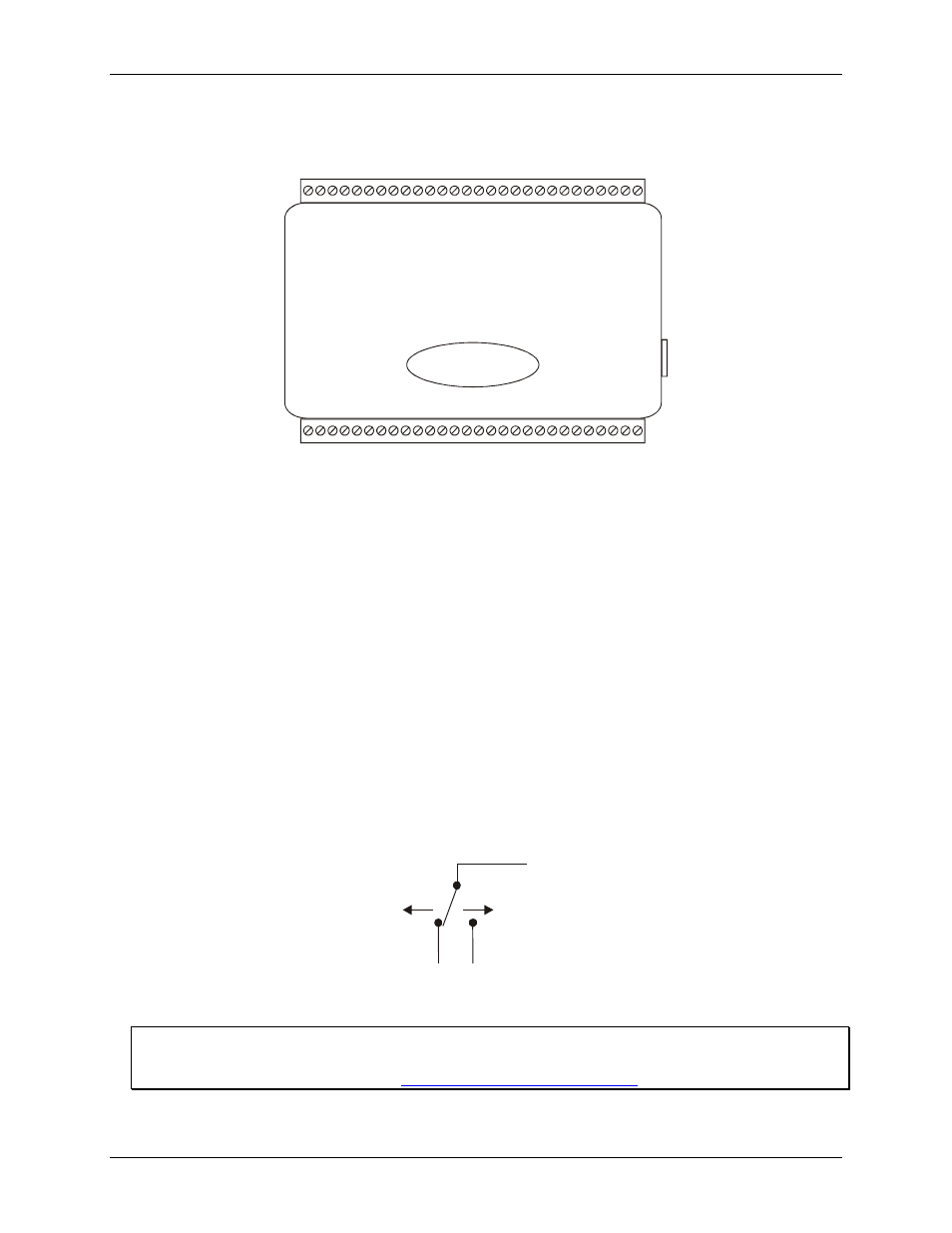
Figure 4. USB-4301 signal pin out
Counter terminals (INP1 to INP5, GAT1 to GAT5, and OUT1 to OUT5)
The counter terminals provide the connections for the clock input signal and gate signal to each counter, and the
output signal from each counter. The clock, gate, and output sources are software-selectable. You can configure
each counter to count up or down.
Digital input (DI0 to DI7) and output (DO0 to DO7) terminals
You can connect up to eight digital input lines to the screw terminals labeled
DI0
to
DI7
(pins 21 through 28),
and up to eight digital output lines to the screw terminals labeled
DO0
to
DO7
(pins 49 through 56).
You can use the digital input terminals to detect the state of any TTL level input. Refer to the schematic shown
in Figure 5. When the switch is set to the +5V input, DI7 reads TRUE (1). If you move the switch to GND, DI7
reads FALSE (0).
+5V
GND
DI
7
Figure 5. Schematic showing switch detection by digital channel DI7
For more information on digital signal connections
For more information on digital signal connections and digital I/O techniques, refer to the Guide to Signal
Connections (available on our web sit