Measurement Computing USB-4301 User Manual
Page 13
USB-4301 User's Guide
Functional Details
13
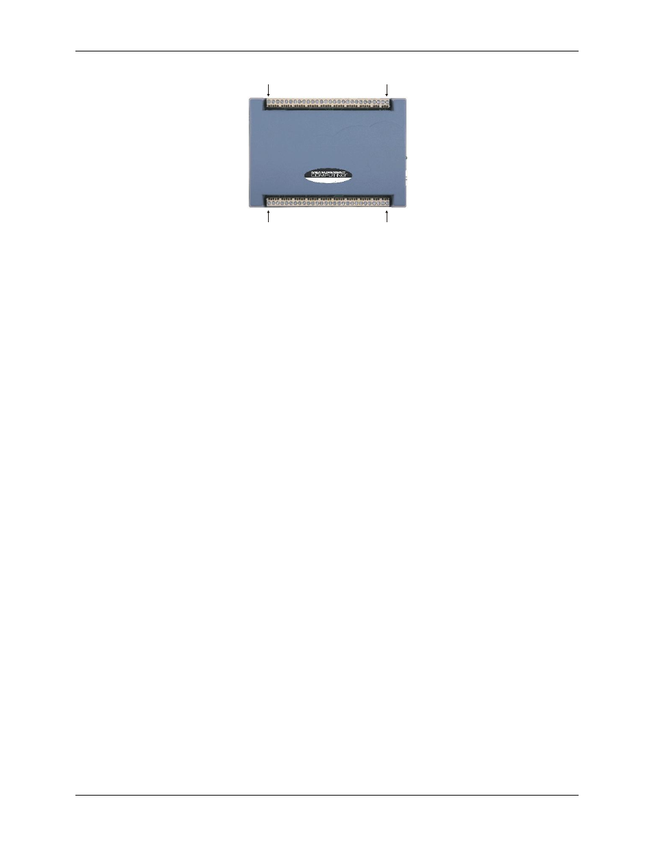
Pin 56
Pin 29
Pin 28
Pin 1
USB-4301
Figure 3. USB-4301 screw terminal pin numbering
Screw terminal – pins 1-28
The screw terminals on the bottom edge of the USB-4301 (pins 1 to 28) provide the following connections:
Two counter input connections (
INP1
and
INP2
)
Two counter gate connections (
GAT1
and
GAT2
)
Two counter output connections (
OUT1
and
OUT2
)
Eight digital input connections (
DI0
to
DI7
)
One pull-up/down control connection (
DI CTL
)
One oscillator output connection (
OSC
)
One interrupt input connection (
INT
)
Two voltage output power connections (
+5V
)
Two ground connections (
GND
)
Seven pins are reserved (
RSVD
). Do not connect signals to these pins.
Screw terminal – pins 29-56
The screw terminals on the top edge of the USB-4301 (pins 29 to 56) provide the following connections:
Three counter input connections (
INP3
–
INP5
)
Three counter gate connections (
GAT3
–
GAT5
)
Three counter output connections (
OUT3
–
OUT5
)
Eight digital output connections (
DO0
to
DO7
)
One pull-up/down control connection (
DI CTL
)
Two ground connections (
GND
)
Nine pins are reserved (
RSVD
). Do not connect signals to these pins.