External components – Measurement Computing USB-4301 User Manual
Page 12
USB-4301 User's Guide
Functional Details
12
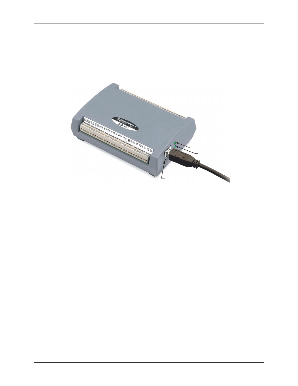
External components
The USB-4301 has the following external components, as shown in Figure 2.
USB connector
Status LED
Power LED
Screw terminal banks (2)
USB
connector
Power LED
Status LED
Screw terminal
pins 1 to 28
Screw terminal
pins 29 to 56
Figure 2. USB-4301 components
USB connector
The USB connector provides power and communication. The voltage supplied through the USB connector is
system-dependent, and may be less than 5 V. No external power supply is required.
Status LED
The Status LED indicates the communication status of the USB-4301. It flashes when data is being transferred,
and is off when the USB-4301 is not communicating. This LED uses up to 10 mA of current and cannot be
disabled.
Power LED
The power LED lights up when the USB-4301 is connected to a USB port on your computer or to an external
USB hub that is connected to your computer.
Screw terminal banks
The USB-4301 has two rows of screw terminals—one row on the top edge of the housing, and one row on the
bottom edge. Each row has 28 connections. Use 16 AWG to 30 AWG wire gauge when making screw terminal
connections. Pin numbers are identified in Figure 3.