7 electronics and interfacing, 1 pull up & pull down resistors – Measurement Computing PCI-DIO48H/CTR15 User Manual
Page 21
7 ELECTRONICS AND INTERFACING
This short introduction to the electronics, most often needed by digital I/O board
users, covers a few key concepts.
IMPORTANT NOTE
WHENEVER THE 8255 (or its emulation) IS POWERED- ON OR
RESET, ALL PINS ARE SET TO HIGH IMPEDANCE INPUT.
The implications of this is that if you have output devices such as solid state relays,
they may be switched on whenever the computer is powered on or reset. To prevent
unwanted switching and to drive all outputs to a known (safe) state after power-on or
reset, pull all pins either high or low through a 2.2K resistor.
7.1 PULL UP & PULL DOWN RESISTORS
Whenever board is powered on or reset, the digital I/O control registers are set to a
known state. That state is mode 0, all ports input. The input bits are of the 74LS
series and will typically (but not certainly) float high when in the input mode. There
may also be enough drive current available from the inputs to turn on connected
devices.
If the inputs of the device you are controlling are left to float, they may float up or
down. Which way they float is dependent on the characteristics of the circuit and the
electrical environment; and may be unpredictable. The result is that your controlled
device may get turned on. That is why you need pull up or pull down resistors.
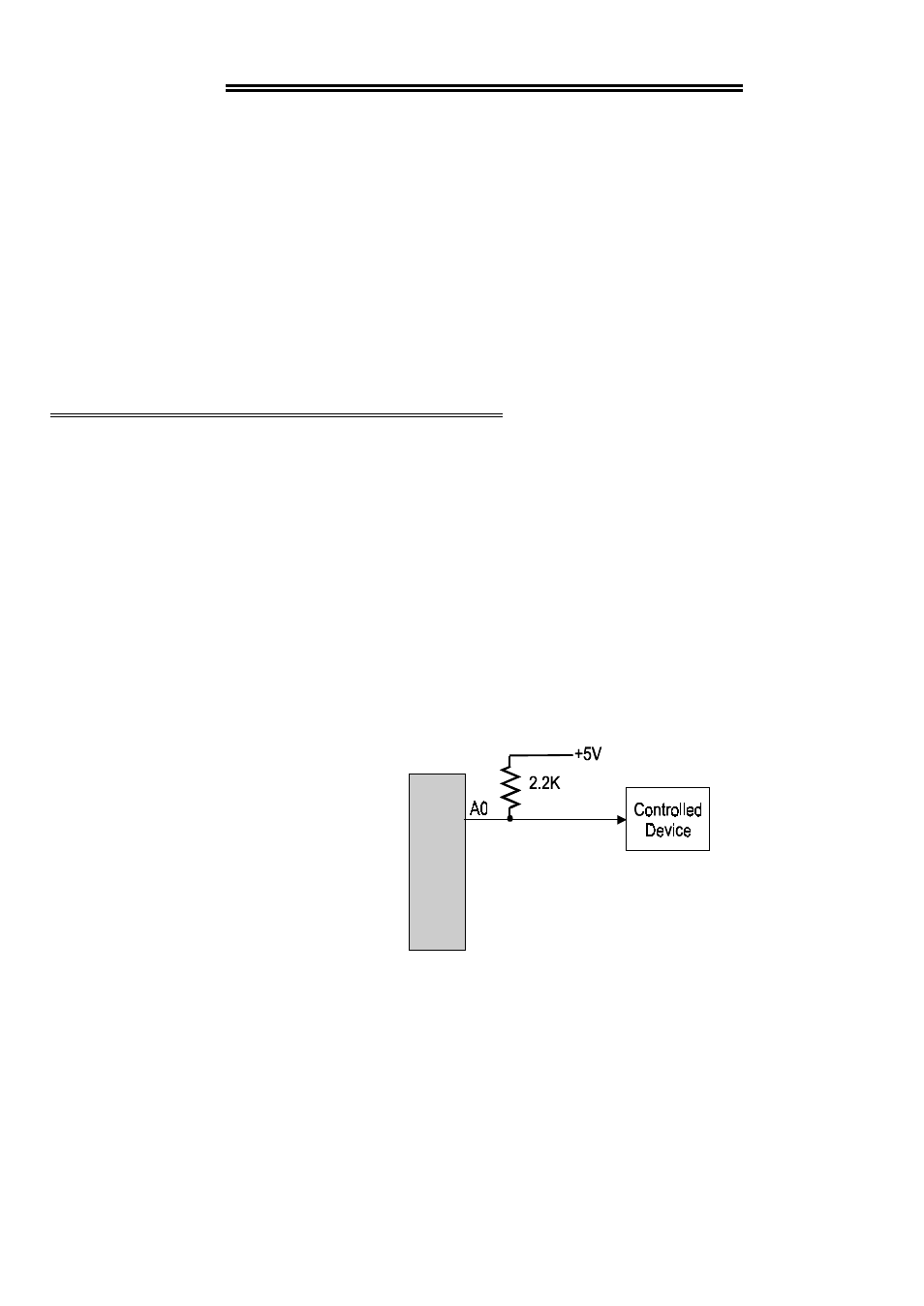
Shown here is one digital output with a
pull-up resistor attached.
The pull-up resistor provides a
reference to +5V while its value of
2200 ohms requires only 2.3 mA of
drive current
If the board is reset and enters high
impedance input, the line is pulled
high. At that point, both the board
AND the device being controlled will
sense a high signal.
Figure 7-1. Pull-Up Resistor Schematic
If the board is in output mode, it has more than enough power (64 mA) to over ride
the pull-up/down resistor's high signal and drive the line to 0 volts.
17
Digital
Output
Circuit