Measurement Computing PCI-DIO48H/CTR15 User Manual
Page 13
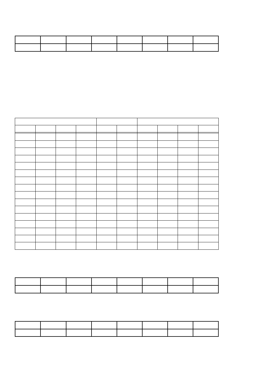
CONTROL REGISTER 1
BADR2 + 03h
WRITE only
D0
D1
-
D3
D4
-
-
-
0
1
2
3
4
5
6
7
The operating mode of the digital I/O ports is Mode 0. The control register therefore
is used to set the ports for inputs or outputs at the connector. For example, to set all
ports to output, write the value 0h to Base + 3. To set all ports to input, write the
value 1Bh to Base + 3. The user can read the current state of an output port by simply
reading that port when configured to be output.
D7, D6, D5, and D2 are ‘don’t care’. They are shown as ‘0’ below. ‘CU’ is PORT C
upper nibble, ‘CL’ is PORT C lower nibble.
Table 5-2. DI/O Configuration Coding
IN
IN
IN
IN
27
1B
1
1
1
1
OUT
IN
IN
IN
26
1A
0
1
1
1
IN
OUT
IN
IN
25
19
1
0
1
1
OUT
OUT
IN
IN
24
18
0
0
1
1
IN
IN
OUT
IN
19
13
1
1
0
1
OUT
IN
OUT
IN
18
12
0
1
0
1
IN
OUT
OUT
IN
17
11
1
0
0
1
OUT
OUT
OUT
IN
16
10
0
0
0
1
IN
IN
IN
OUT
11
B
1
1
1
0
OUT
IN
IN
OUT
10
A
0
1
1
0
IN
OUT
IN
OUT
9
9
1
0
1
0
OUT
OUT
IN
OUT
8
8
0
0
1
0
IN
IN
OUT
OUT
3
3
1
1
0
0
OUT
IN
OUT
OUT
2
2
0
1
0
0
IN
OUT
OUT
OUT
1
1
1
0
0
0
OUT
OUT
OUT
OUT
0
0
0
0
0
0
CL
CU
B
A
Dec
Hex
D0
D1
D3
D4
DIO PORT
VALUES
CONTROL REG. CODES
PORT 2A DATA
BADR2 + 04h
READ/WRITE
A0
A1
A2
A3
A4
A5
A6
A7
0
1
2
3
4
5
6
7
PORT 2B DATA
BADR2 + 05h
READ/WRITE
B0
B1
B2
B3
B4
B5
B6
B7
0
1
2
3
4
5
6
7
9