Measurement Computing PCI-DIO48H/CTR15 User Manual
Page 12
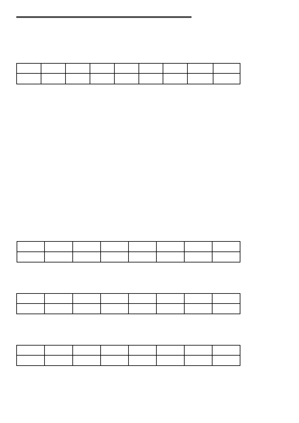
5.1 PCI-DIO48H/CTR15 REGISTER DESCRIPTION
INTERRUPT STATUS/CONTROL
BADR1 + 4Ch
READ/WRITE
INTE
INTPOL
INT
x
x
x
x
x
x
0
1
2
3
4
5
6
7
31:8
This register, as with all the 9052 registers, is 32 bits long. Since the rest of the
register has specific control functions, they must be masked off when accessing the
interrupt control functions.
INTE
Interrupt Enable
0 = disabled
1 = enabled (default).
INTPOL Interrupt
Polarity
0 = active low (default)
1 = active high.
INT Interrupt
Status
0 = interrupt is not active
1 = interrupt is active.
The digital I/O ports emulate 8255, Mode 0 operation.
PORT 1A DATA
BADR2 + 00h
READ/WRITE
A0
A1
A2
A3
A4
A5
A6
A7
0
1
2
3
4
5
6
7
PORT 1B DATA
BADR2 + 01h
READ/WRITE
B0
B1
B2
B3
B4
B5
B6
B7
0
1
2
3
4
5
6
7
PORT 1C DATA
BADR2 + 02h
READ/WRITE
CL0
CL1
CL2
CL3
CH0
CH1
CH2
CH3
0
1
2
3
4
5
6
7
8
See also other documents in the category Measurement Computing Hardware:
- ACC-300 (7 pages)
- AI-EXP32 (20 pages)
- AI-EXP48 (19 pages)
- BTH-1208LS (30 pages)
- 6K-ERB08 (32 pages)
- BTH-1208LS Quick Start (4 pages)
- 6K-SSR-RACK08 (33 pages)
- BTH-1208LS-OEM (27 pages)
- CB-COM-Digital (68 pages)
- CB-7018 (68 pages)
- CB-7000 Utilities (44 pages)
- CB-7080D (74 pages)
- CB-COM-7033 (44 pages)
- CB-COM-7017 (72 pages)
- CB-COM-7024 (76 pages)
- CB-NAP-7000P (36 pages)
- CIO-DAC02/16 (16 pages)
- CIO-DAC02 (18 pages)
- CB-NAP-7000D (56 pages)
- CIO-DAC16-I (16 pages)
- CIO-DAC16/16 (20 pages)
- CIO-DAS08 (21 pages)
- CIO-DAC16 (20 pages)
- CIO-DAS08/JR (16 pages)
- CIO-DAS08/JR/16 (14 pages)
- CIO-DAS08/JR-AO (16 pages)
- CIO-DAS08-AOM (32 pages)
- CIO-DAS08-PGM (28 pages)
- CIO-DAS16/330 (34 pages)
- CIO-DAS48-I (17 pages)
- CIO-DAS16/M1 (38 pages)
- CIO-DAS48-PGA (18 pages)
- CIO-DAS800 (20 pages)
- CIO-DAS802/16 (22 pages)
- CIO-DAS6402/16 (40 pages)
- CIO-DAS-TEMP (20 pages)
- CIO-DDA06/16 (18 pages)
- CIO-DDA06/JR (17 pages)
- CIO-DIO24H (20 pages)
- CIO-DIO24/CTR3 (21 pages)
- CIO-DI192 (24 pages)
- CIO-DDA06 (21 pages)
- CIO-DIO48 (19 pages)
- CIO-DO192H (16 pages)
- CIO-DIO192 (20 pages)