Ch 7 - analog output modules, Pointscan/217 & pointscan/216, Overview – Measurement Computing PointScan 200 Series rev.1.0 User Manual
Page 29: Wiring, I/o registers, 7 - analog output modules, Pointscan/217, 8 channel 4-20 ma analog, Output module, Pointscan/216
PointScan/200 User’s Manual
9-12-01
Combination I/O Modules 7-1
Analog Output Modules
7
Note:
It is not necessary to recalibrate analog I/O if a logic module is replaced.
Analog logic modules may be hot swapped and will not require recalibration. User calibration data is stored
in system memory outside of the analog module. Factory calibration data is stored in memory in the plug-in
logic module. Since all logic modules are calibrated to the same factory standards, recalibration is not
necessary if logic modules are moved or replaced.
PointScan/217
8 Channel 4-20 mA Analog Output Module
PointScan/216
4 Channel 4-20 mA Analog Output Module
Overview
These analog output modules provide 4-20 mA signals as proportional control for process signals or to
drive chart recorders or other measurement devices. More information may be found in the on-line help
supplied with the IO Toolkit.
Number of Channels
4 or 8 (13 bit resolution -- 0.03% of full scale)
Output Range
4 - 20 mA
Load Resistance Range
0 - 750 ohms (at a supply voltage of 24 VDC)
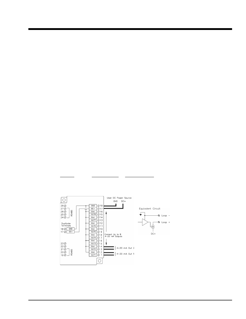
Wiring
Two terminals are provided for each output channel. Outputs are directly powered from the DC power
connected to this module.
Note:
Both modules use a PointScan/217 wiring base. Only the first four channels are used on the
PointScan/216. System capacity may be increased by plugging a
PointScan/217 eight channel module into a base previously occupied by a PointScan/216 four channel
module.
I/O Registers
Function
IOtech Registers
Modbus Registers
Analog Outputs
AY0 - AY7
40001 - 40008 Positive values: 0
Æ 32767
Note: Only the first four registers are used on the PointScan/216.