Digital input port connector pinouts – Measurement Computing Digital HS User Manual
Page 36
1
19
20
37
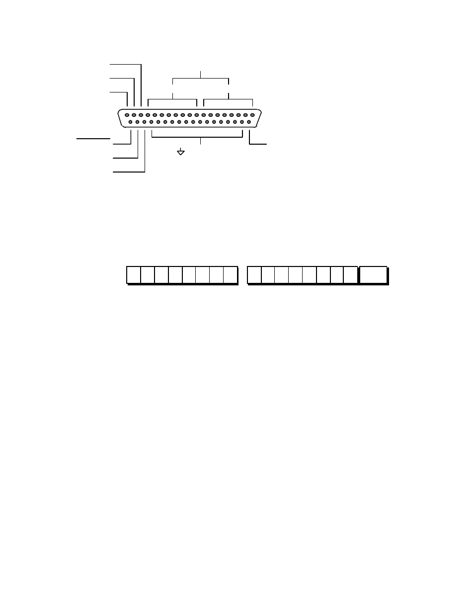
+5 volts
Common
iRESET
SB2
SB1
1
8
9
16
Second Byte
First Byte
DIN15 - DIN0
iBusy
iDAV
iEND
17
18
19
37
36
35
34
21
20
Digital Input Port Connector Pinouts
15 14 13 12 11 10 9
8
7
6
5
4
3
2
1
0
iEND
Second Byte
First Byte
DIN0 Thru DIN15
Input Port Organization
First Byte, Second Byte and iEND Bit Organization
Both the first byte and second byte port data are latched simultaneously on the active
edge of the iDAV handshake line.
3.2.1 Input Port Handshake Lines (iDAV and iBusy)
Data to the input port should not be written while the handshake line, iBusy, is active.
When sensed inactive, all 17 bits of data can be presented to the input lines followed
by a minimum delay of 50 ns, after which iDAV can be forced active.
The leading transition of the iDAV line latches data into the input latches. The iBusy
signal, when active, causes subsequent leading edge transitions of iDAV to be
ignored until the iBusy signal becomes inactive. When iDAV senses active, iBusy is
forced active until all data have been transferred to the IEEE 488 bus listener. The
iDAV line must then go inactive for a minimum duration of 150 ns following the
inactive state of iBusy before additional data can be detected on the input port.