P3 and p5 pin assignments – Measurement Computing ADAC/5500 Series Installation User Manual
Page 12
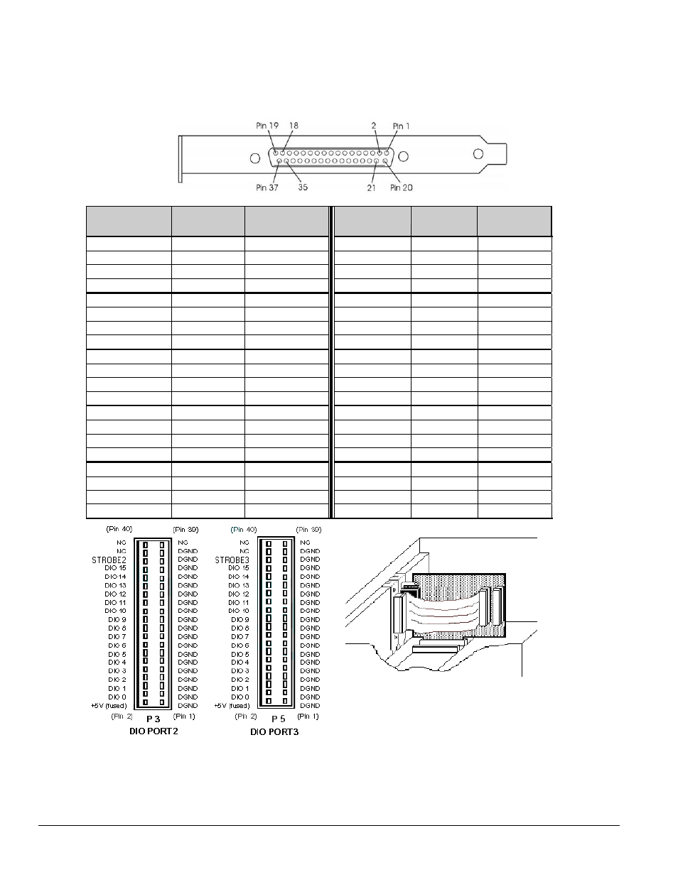
P3 and P5 Pin Assignments
The ADAC/5501MF, ADAC/5502MF, ADAC/5503HR and ADAC/5504HR include two auxiliary 40-pin headers. These
are located on the back of the boards, and provide access to the two 16-bit DIO ports (DIO2 and DIO3). Two CA-G17-
ADAC cables can be used to bring the DIO2 and DIO3 headers to separate37-pin D-type connectors [one GA-17 cable per
DIO header]. GA17’s orb (following figure) mounts at the back of the host PC.
The DB37-end of a CA-G17-ADAC Cable, which includes an Orb for PC Mounting
SIGNAL NAME
P3 PIN or
P5 PIN
G17 PIN
(37-pin D)
SIGNAL NAME
P3 PIN or
P5 PIN
G17 PIN
(37-pin D)
DGND 1
1 DGND
21 11
+ 5 V (fused)
2
20
D9
22
30
DGND 3
2 DGND
23 12
D0 4 21 D10
24
31
DGND 5
3 DGND
25 13
D1 6 22 D11
26
32
DGND 7
4 DGND
27 14
D2 8 23 D12
28
33
DGND 9
5 DGND
29 15
D3 10 24 D13
30
34
DGND 11
6
DGND
31 16
D4 12 25 D14
32
35
DGND 13
7
DGND
33 17
D5 14 26 D15
34
36
DGND 15
8
DGND
35 18
D6
16
27
STROBE2 / 3
36
37
DGND 17
9
DGND
37 19
D7 18 28 DGND
38
n/c
DGND 19 10 DGND
39 n/c
D8 20 29 DGND
40
n/c
P3 & P5 Auxiliary Digital I/O Connectors
Standard 40-Pin Male Headers
A CA-G17-ADAC Cable, Installed
Signal definitions for the P3 and P5 Auxiliary 40-Pin DIO headers and the DB37 connector follow.
12 ADAC/5500 Series Installation Guide
908096
1107-0940, rev 2.0