Pinouts, J1 pin assignments for adac/5500mf only – Measurement Computing ADAC/5500 Series Installation User Manual
Page 10
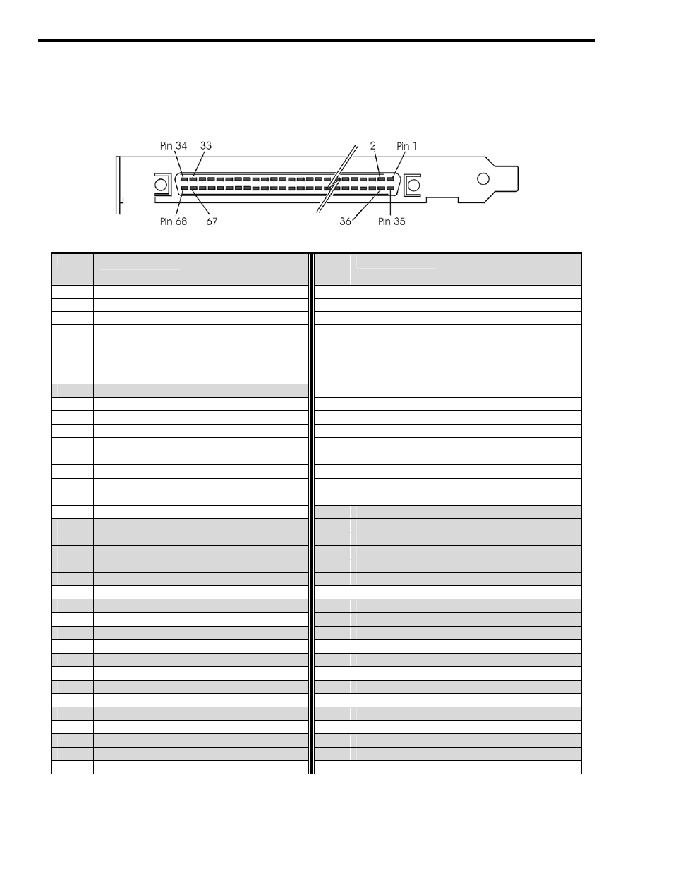
Pinouts
This section contains pinouts for the various ADAC/5500 Series Boards and the terminal boards that can be used
with them, i.e., ADAC-TB-8, ADAC-TB-16, and DC-37.
J1 Pin Assignments for ADAC/5500MF Only
Standard 68-Pin SCSCI Type III, Socket (Female) Connector with Orb
Pin
Signal
Description /
Comments
Pi
n
Signal
Description / Comments
1
DGND
Digital Ground
35
+5 V (fused)
Power
2 +15
V
(fused) Power 36
+5
V
(fused)
Power
3
-15 V (fused)
Power
37
+5 V (fused)
Power
4
ADTGOUT / TMR0
Internal ADC Trigger Output
/ Timer 0 Clock Output
38
ADTGIN
External Gate (level controlled),
or External Trigger (edge active)
5
ADCLKOUT / TMR1
Internal ADC Trigger Output
/ Timer 1 Clock Output
39
ADCLKIN / CNTR0
External ADC Clock In, or
Counter 0. Rising or Falling
Edge Sensitive.
6
N/C
Not Connected
40
CNTR1
Counter 1 Clock Input
7
DIO_15
TTL Level Digital I/O Ch. 15
41
DIO_14
TTL Level Digital I/O Ch. 14
8
DIO_13
TTL Level Digital I/O Ch. 13
42
DIO_12
TTL Level Digital I/O Ch. 12
9
DIO_11
TTL Level Digital I/O Ch. 11
43
DIO_10
TTL Level Digital I/O Ch. 10
10
DIO_9
TTL Level Digital I/O Ch. 9
44
DIO_8
TTL Level Digital I/O Ch. 8
11
DIO_7
TTL Level Digital I/O Ch. 7
45
DIO_6
TTL Level Digital I/O Ch. 6
12
DIO_5
TTL Level Digital I/O Ch. 5
46
DIO_4
TTL Level Digital I/O Ch. 4
13
DIO_3
TTL Level Digital I/O Ch. 3
47
DIO_2
TTL Level Digital I/O Ch. 2
14
DIO_1
TTL Level Digital I/O Ch. 1
48
DIO_0
TTL Level Digital I/O Ch. 0
15 DGND
Digital
Ground
49
N/C
Not Connected
16
N/C
Not Connected
50
N/C
Not Connected
17
N/C
Not Connected
51
N/C
Not Connected
18
N/C
Not Connected
52
N/C
Not Connected
19
N/C
Not Connected
53
N/C
Not Connected
20
N/C
Not Connected
54
N/C
Not Connected
21
AGND
Analog Ground
55
AGND
Analog Ground
22
N/C
Not Connected
56
N/C
Not Connected
23 SGND
Signal
Ground
57
N/C
Not Connected
24
N/C
Not Connected
58
N/C
Not Connected
25
AIN_7
Analog Input, Ch. 7
59
AIN_3
Analog Input, Ch. 3
26
N/C
Not Connected
60
N/C
Not Connected
27
AIN_6
Analog Input, Ch. 6
61
AIN_2
Analog Input, Ch. 2
28
N/C
Not Connected
62
N/C
Not Connected
29
AIN_5
Analog Input, Ch. 5
63
AIN_1
Analog Input, Ch. 1
30
N/C
Not Connected
64
N/C
Not Connected
31
AIN_4
Analog Input, Ch. 4
65
AIN_0
Analog Input, Ch. 0
32
N/C
Not Connected
66
N/C
Not Connected
33
N/C
Not Connected
67
N/C
Not Connected
34
AGND
Analog Ground
68
DGND
Digital Ground
10 ADAC/5500 Series Installation Guide
908096
1107-0940, rev 2.0