Measurement Computing WBK40 User Manual
Page 24
You will need the following:
Phillips Screwdriver
•
•
•
•
•
3AG Fuse Puller, or needle-nose pliers*
3/16-inch hex-nut driver
Grounding wrist strap and associated anti-static pad
Replacement fuse F201
*
Needle-nose pliers can be used to pull MINI ATO fuses; but should not be used to insert fuses.
Observe the Caution and the important note on page 23 of this document module prior to
beginning this fuse replacement procedure.
1. If you have not already done so, turn OFF the power to, and UNPLUG the WBK40 or WBK41 module
and all connected equipment. Remove all signal I/O lines from the unit.
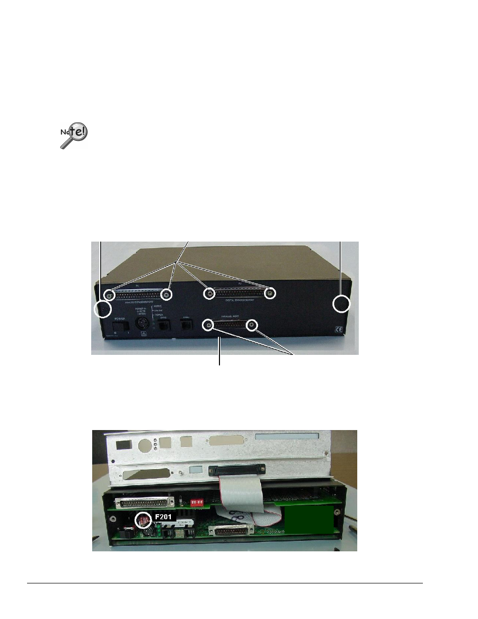
2. Remove the Jackscrews from the P1 and PARALLEL PORT connectors. In addition, WBK41 users must
remove Jackscrews from the P2 connector. The following figure shows the screw locations.
3. Using a Phillips screwdriver, remove the two Rear Panel Screws and the Bottom Panel Screw.
Rear Panel Screw P1 and P2 Jackscrews* Rear Panel Screw
WBK41 Rear Panel, Screw Removal
*
WBK40 has no P2 connector
.
Bottom Panel Screw
Parallel Port Jackscrews
4. Remove the Rear Panel from the rest of the chassis.
F201 Fuse Location
pg. 24, WBK40 & WBK41
926896
Thermocouple and Multifunctional Modules