Caution – Measurement Computing WBK40 User Manual
Page 12
Channel Input Side Device Interface Side
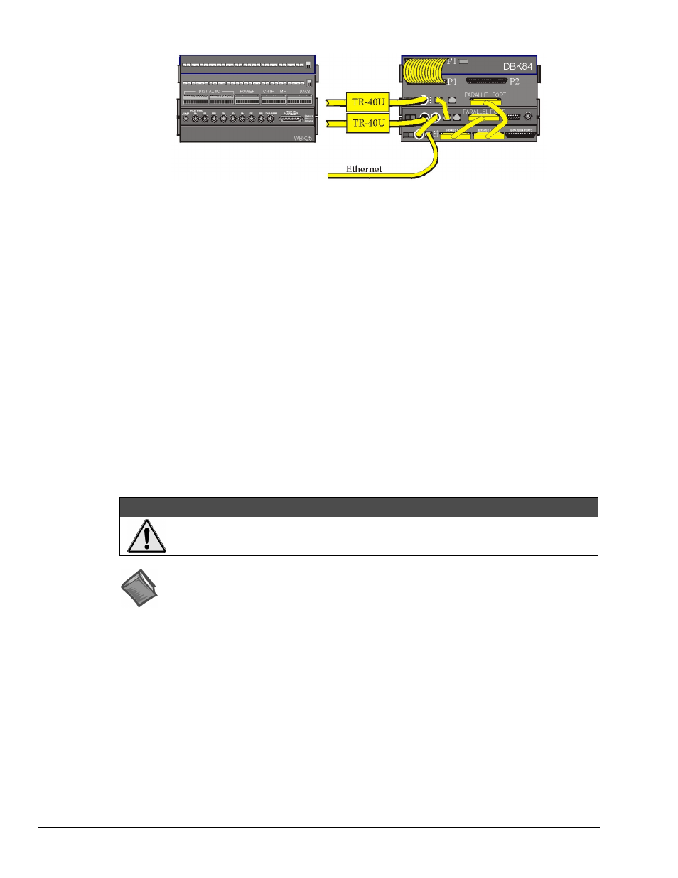
A WaveBook/516A with a WBK25, WBK41, and DBK84
Note 1
DBK84
WBK41
WaveBook/516A
WBK25
Device Interface Connections (seen in the above example):
1. From the WBK41 P1 connector to the DBK84 Module via one CA-37-1T Cable.*
2. From a WBK41 SYNC port to a WaveBook/516A SYNC Port via CA-74-1 Cable.
3. From the WBK41 PARALLEL PORT connector to the WBK25 EXPANSION PORT 2 connector via a
CA-35-12 cable.
4. From the WaveBook/516A PARALLEL PORT to the WBK25 EXPANSION PORT 1 connector via a
CA-35-12 cable.
5. From the WBK25 ETHERNET port to the Ethernet via a CA-242 cable.
6. Power Supply – a TR-40U was connected to the POWER IN [DIN 5] connector to supply
power at +10 VDC to +30 VDC for the WBK41 and the WaveBook/516A.
7. Power Supply – From the WaveBook/516A’s POWER OUT [DIN 5] +10 VDC to +30 VDC connector to
the WBK25’s POWER IN [DIN 5] connector via a CA-115 power cable. The CA-115 is a 6-inch long
cable which has a 5-pin DIN male connector at each end.
CAUTION
An incorrect use of power can damage equipment or degrade performance. Prior to
connecting your devices to power, calculate your system’s power requirements.
Reference Note
Information pertaining to connecting the system to power and calculating the amount of
power needed can be found in the WaveBook User’s Manual. A PDF version is included on
the data acquisition CD and can be accessed from the CD’s intro-screen by using the
* Information regarding the use of CA-37-T cables is provided on page 10.
Using Fastener Panels to Stack Modules:
Fastener Panels are discussed on page 7.
Note 1: Each DBK84 module requires a unique address setting as explained on page 13.
pg. 12, WBK40 & WBK41
926896
Thermocouple and Multifunctional Modules