Usb-erb24 block diagram, Software features, Usb-erb24 block diagram -2 – Measurement Computing USB-ERB24 User Manual
Page 9: Software features -2, Usb-erb24 user's guide introducing the usb-erb24, Figure 1-2. usb-erb24 functional block diagram
USB-ERB24 User's Guide
Introducing the USB-ERB24
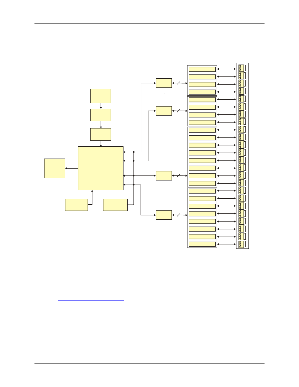
USB-ERB24 block diagram
USB-ERB24 functions are illustrated in the block diagram shown here.
USB
Microcontroller
500 mA
USB 2.0
compliant
interface
Power
Regulator
Power
Monitor
9.0 V
External
Power
Switch S2
(pull-up/down)
Switch S1
(inv/non-inv)
Relay 24
Relay
driver
4
Relay
driver
Relay
driver
4
Relay
driver
Relay
driver
8
Relay
driver
Relay
driver
8
Relay
driver
Screw terminal
Relay 23
Relay 22
Relay 21
Relay 20
Relay 19
Relay 18
Relay 17
Relay 16
Relay 15
Relay 14
Relay 13
Relay 12
Relay 11
Relay 10
Relay 9
Relay 8
Relay 7
Relay 6
Relay 5
Relay 4
Relay 3
Relay 2
Relay 1
NO
C
NC
C
NO
C
NC
C
NO
C
NC
C
NO
C
NC
C
NO
C
NC
C
NO
C
NC
C
NO
C
NC
C
NO
C
NC
C
NO
C
NC
C
NO
C
NC
C
NO
C
NC
C
NO
C
NC
C
NO
C
NC
C
NO
C
NC
C
NO
C
NC
C
NO
C
NC
C
NO
C
NC
C
NO
C
NC
C
NO
C
NC
C
NO
C
NC
C
NO
C
NC
C
NO
C
NC
C
NO
C
NC
C
NO
C
NC
C
24
23
22
21
20
19
18
17
16
15
14
13
12
11
10
9
8
7
6
5
4
3
2
1
Figure 1-2. USB-ERB24 functional block diagram
Software features
For information on the features of InstaCal and the other software included with your USB-ERB24, refer to the
Quick Start Guide that shipped with your device. The Quick Start Guide is also available in PDF at
.
r the latest software version or versions of the software supported
under less commonly used operating systems.
1-2