Pull-up/pull-down switch (s2), Screw terminals, Daisy chaining additional relays to the usb-erb24 – Measurement Computing USB-ERB24 User Manual
Page 17: Pull-up/pull-down switch (s2) -3, Screw terminals -3
USB-ERB24 User's Guide
Functional Details
Pull-up/pull-down switch (S2)
The Pull-up/pull-down switch (S2) sets the power-on state of each relay bank. By default, switch S2 is
configured for pull-down (relays inactive at power-up – see
).
Figure 3-3. Switch S2 default configuration
S2
PULL UP
PULL DOWN
CL
CH
A
B
The switch labeled
A
configures relays 1 through 8, the switch labeled
B
configures relays 9 through 16, the
switch labeled
CH
configures relays 17 through 20, the switch labeled
CL
configures relays 21 through 24.
PULL UP
: the relay energizes at power-up, regardless of the state of switch S1.
PULL DOWN
: the relays are not energized at power-up.
Use InstaCal to read the current power-on state setting for each module group.
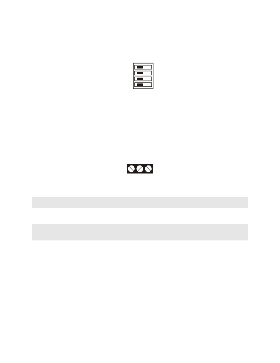
Screw terminals
Connect external devices to the relay contacts using the USB-ERB24 board's 24 sets of screw terminals. Each
relay has a normally closed (NC), common (C), and normally open (NO) contact.
terminals on a typical relay channel.
Figure 3-4. Typical relay channel
NC C NO
Each screw terminal is identified with a label on the board and on the underside of the enclosure lid.
Caution!
Before connecting wires to the screw terminals, turn off the power to the USB-ERB24, and make
sure that the signal wires do not contain live voltages.
Use 12-22 AWG wire for your signal connections. Properly insulate the wires to avoid any short circuit to the
other channels, ground, or other points on the board.
Caution!
Keep the length of stripped wire at a minimum to avoid a short to the enclosure! When
connecting your field wiring to the screw terminals, use the strip gage on the terminal strip, or strip
to 5.5 - 7.0 mm (0.215" to 0.275") long.
Daisy chaining additional relays to the USB-ERB24
Daisy chained MCC USB Series products connect to the USB bus through the high-speed hub on the USB-
ERB24. You can daisy chain a maximum of four MCC USB Series products to a single USB 2.0 port or USB
1.1 port on your computer.
MCC USB Series products are USB 1.1 full-speed devices that provide a signaling bit rate of 12 Mb/s. The
throughput rate is shared by all devices connected to the USB bus.
Use the supplied cable or an equivalent full-speed cables cable when daisy chaining to additional MCC USB
Series products.
To daisy chain two or more USB-ERB24 relay boards, follow the steps below. This procedure assumes you
already have one USB-ERB24 connected to a computer and to an external power source. The USB-ERB24
already connected to the computer is referred to as the connected module. The USB-ERB24 you want to daisy
chain to the connected board is referred to as the new module.
3-3